Member
Joined 2009
Paid Member
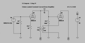
I was looking at the constant current draw amplifier (Broskie labels it the CCDA) and wondering if I could realize this design using chokes. The reason being to preserve it's performance at lower B+ where resistor loading drops too many volts. So the anode of the input valve is choke loaded and the cathode of the output valve is choke loaded.
And I got to thinking that the possibility of both dc and ac constant current draw through these two chokes allows the use of a dc-balanced transformer. Typically a transformer without a 'gap' has fewer tradeoffs in performance.
Note: output is from the cathode of the 2nd valve.
What advantages and disadvantages do you see with this ?
Attachments
Normal 'constant-current' amps are only constant current when there is no load. On the other hand, an anode choke means the first stage is constant current on its own!
Note that two chokes wound on the same core is normally called a transformer. Coupling the two stages together with a transformer as well as a capacitor could have interesting results.
Note that two chokes wound on the same core is normally called a transformer. Coupling the two stages together with a transformer as well as a capacitor could have interesting results.
Member
Joined 2009
Paid Member
Note that two chokes wound on the same core is normally called a transformer.
isn't that what I said

Coupling the two stages together with a transformer as well as a capacitor could have interesting results.
that's what I'm thinking - but not sure exactly what it means!
Looks like the 1st stage will have a problem driving the grid since it has got both AC phases fighting each other in the xfmr. I tried moving the xfmr sec. to the output plate but the problem then is with the DC.
On second look, I think it does work if you move the secondary to the output plate. (undotted end to the output plate) Needs an attenuation for the output grid drive then. Just a self splitting class A P-P then.
On second look, I think it does work if you move the secondary to the output plate. (undotted end to the output plate) Needs an attenuation for the output grid drive then. Just a self splitting class A P-P then.
Last edited:
Member
Joined 2009
Paid Member
smoking-amp, you're right, in order for the dc currents to cancel, the ac currents need to be out of phase between primary and secondary. This is intentional and is what makes it interesting --- I'm wondering if it doesn't increase the effective inductance of the load seen by each valve.
The load impedance seen by the plate of the 1st tube will be something like 1/gm of the second tube due to the xfmr phasing. (almost a dead short, so nearly zero output) What you have is a Schade neg. fdbk. setup with 100% Nfdbk.
Normally an AC load on a constant current setup would cause the current balance to be thrown off, but here I don't think any output can be generated to unbalance it.
Keep experimenting, maybe something different. Could try the primary in the cathode side of the 1st tube. Looks like that will work for AC and DC.
Last edited:
Member
Joined 2009
Paid Member
I have sworn myself off simulations... but just this once.... the toplogy seems to work fine, there is real voltage gain at the output and distortion looks quite reasonable. Not sure if it's Schade -ve feedback from the 2nd stage to the 1st stage, or feedforward from the 1st stage to the 2nd ???
I have found sims to be really great predictors of functionality. Swap the K factor around a bit and see your gain go from 30dB to -5db with the hookup you mention. This strikes me as a red flag for a quirky design and the only thing to do is build it and see which sim is right
dave
dave
Member
Joined 2009
Paid Member
I tried it with perfect coupling coefficient and the gain (c.f. input) is still positive although lower. But transformers aren't perfect and gain is likely to be achieved with a practical unit. I guess the coupling coefficient determines the level of schade feedback, but distortion doesn't seem to be that much different.
Anyhow, I've attached my spice model (change file extension from .txt to .asc before running it under LTSpice)
Anyhow, I've attached my spice model (change file extension from .txt to .asc before running it under LTSpice)
Attachments
- Status
- This old topic is closed. If you want to reopen this topic, contact a moderator using the "Report Post" button.
- Home
- Amplifiers
- Tubes / Valves
- Choke Loaded Const. Current Draw Amp