Hello,
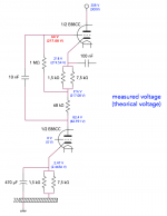
I've been working in a diy audio proyect that is described in this post http://www.diyaudio.com/forums/tubes-valves/190955-troubles-when-elevating-lt-supply.html. I managed to solve the issue about the relay that was causing the problem, so the PSU is now working perfectly. I was able to made some tests. The preamplier works but not properly. I noticed a problem in the upper tube of the mu-follower stages (the setup in the preamplifier is the following: a solid state based buffer + mu-follower + Baxandall tone control + mu-follower). I used a couple of E88CC bottles: one for the lower tubes and the other for the upper tubes. I used an elevated supply for the heaters of upper tubes so that cathode to heater voltage rating is not exceeded (the supply is elevated like 220 Volts). All measured voltages seems to be OK but one: upper tube grid voltage. I am getting 64 Volts instead of about 217 Volts, so the upper tube is off. I swapped the bottles to check that is not a problem in a tube. Apparently, all conections are done properly. The problem is observed in both mu-follower stages. The design is almost equal to the one that can be found in Morgan Jones book. I used PSpice to make the simulations. I attached a schematic with the measurements so that you can compare them with theorical values.
Do you have any ideas of why the grid of the upper tube is getting that low voltage?
Thanks for your help!
Jesús.
Attachments
Hi !
Assuming the tubes are intact and working properly, the voltages can never describe a static state in that schematic. Looking at the lower cathode voltage and cathode resistor, a current of 2mA is flowing. On the other hand the upper tube's grid is at -154V in reference to its cathode ! It is completely shut off. Not a single electron would escape that potential")
So please check:
Is the tube working ? just swap around a bit and see if that happens again.
Is the circuit oscillating ?
Some other hints: Yupp, you can avoid decoupling caps at the cathode, but it's not useful. You don't have the usual case of a gain reduction due to current feedback (series derived, series applied) because the load resistance is nearly infinite. You have to imagine this like kind of a fight. feedback wants to reduce gain, but the upper tube tries everything to give the lower tube a constant current. Just the tiny error of the CCS (upper tube) (since the upper tube is a triode it's not even so tiny) will be feedback in the lower tube. Futhermore the anode resistance of the lower tube rises. At all, this is not useful. Just give the lower cathode a decoupling cap.
Another is thing concerns the quiescent current. In my opinion a ECC88 sounds much better with more current flowing. Aroud 7 - 8 mA is a good value. But that is something you have to find out for yourself.
Assuming the tubes are intact and working properly, the voltages can never describe a static state in that schematic. Looking at the lower cathode voltage and cathode resistor, a current of 2mA is flowing. On the other hand the upper tube's grid is at -154V in reference to its cathode ! It is completely shut off. Not a single electron would escape that potential
So please check:
Is the tube working ? just swap around a bit and see if that happens again.
Is the circuit oscillating ?
Some other hints: Yupp, you can avoid decoupling caps at the cathode, but it's not useful. You don't have the usual case of a gain reduction due to current feedback (series derived, series applied) because the load resistance is nearly infinite. You have to imagine this like kind of a fight. feedback wants to reduce gain, but the upper tube tries everything to give the lower tube a constant current. Just the tiny error of the CCS (upper tube) (since the upper tube is a triode it's not even so tiny) will be feedback in the lower tube. Futhermore the anode resistance of the lower tube rises. At all, this is not useful. Just give the lower cathode a decoupling cap.
Another is thing concerns the quiescent current. In my opinion a ECC88 sounds much better with more current flowing. Aroud 7 - 8 mA is a good value. But that is something you have to find out for yourself.
Looks like its oscillating to me....
Have you grid-stoppers in place on both triodes?
200 ohm or some such value would be OK, The ECC88 was developed for VHF 'RF' duty anyway, so layout could inadvertantly made a VHF oscillator!
There's no need for such a high value grid-resistor for the upper triode, you can if you want reduce this to 100K. Its 'bootstrapped' so will not have bad effects using a lower value....
Are the tubes OK? --No H/K shorts?
I think You are correct. He has problem in both stages so I would check if coupling caps have correct voltage rating.10nF is leaky?
if the other voltages are correct then everything is probably alright and they are all almost spot on to where they should be. if the upper tube is cut off then the lower tube cannot work as they are in series - but it is, so everything is probably fine. the reason you get strange readings is that it is not possible with a normal DVM, to measure the voltage on self biased cathode followers' grids (the upper tube) due to bootstrapping creating a very high impedance. rather measure the gain and if you can, distortion.
This most likely just a measurement problem - trying to measure high voltages on high impedance grids is very difficult - even if your meter has a 1Meg or more input resistance it will pull down the grid. I have seen this many times on perfectly functional mu and cathode followers. The way to check it is working OK is to measure the voltage on either end of the cathode resistors.
Cheers
Ian
Cheers
Ian
Hello,
+1
It looks like ruffrecords is onto something. The voltage drop between the B+ and the plate of the bottom triode is near dead on what your model shows. That means that the current flowing is also on target. Getting the correct voltage drop and current would not happen with a far off target controlling grid voltage.
DT
All just for fun!
Ok, thank you all for your answers. I checked that the tubes don't have cathode to heater shorts (that was a problem in an E88CC that I had to replace). As I can see it seems to be a problem in grid voltage measurement, as ruffrecords pointed out, or leakage from 10 nF capacitor, because all other voltages seems to be ok. I note down your suggestions about reducing the grid resistor of upper valves and adding grid-stopper resistors to avoid HF oscillation.
Overall, the amplifier works and the volume control seems to increase gain (actually, input level seen by the stages). It is very quiet, no hum/noise at all. But, appart from those voltages, there are other issues: I sometimes listen some quiet discrete random noises. They can be compared with the noise that is produced when turning on a dirty/old potentiometer but more quietly. Initially, I thought that was caused by electrons that escape from rectifier tube (one E88C tube is fairly close to the rectifier bottle). To overcome this I wrapped the rectifier with a grounded aluminum foil to screen it. Noises didn't dissapear. Moreover, when turning volume or bass boost at full scale the sound is heavily distorted. Keeping volume at half scale makes sound acceptable.
Overall, the amplifier works and the volume control seems to increase gain (actually, input level seen by the stages). It is very quiet, no hum/noise at all. But, appart from those voltages, there are other issues: I sometimes listen some quiet discrete random noises. They can be compared with the noise that is produced when turning on a dirty/old potentiometer but more quietly. Initially, I thought that was caused by electrons that escape from rectifier tube (one E88C tube is fairly close to the rectifier bottle). To overcome this I wrapped the rectifier with a grounded aluminum foil to screen it. Noises didn't dissapear. Moreover, when turning volume or bass boost at full scale the sound is heavily distorted. Keeping volume at half scale makes sound acceptable.
From your initial description you have two mu followers with a (presumably passive) tone control stage in between. I suspect you distortion problems are simply overload due to excessive gain. A mu follower has a gain close to the mu of the tube which for the ECC88 is about 35 if memory serves or about 31dB. Even allowing 20dB loss in your tone control the total avaliable gain at full volume is:
31 + 31 - 20 = 42dB which is huge for a preamp. With the volume control full up, a 2V pp input from a CD player will cause the last mu follower to attempt to output 200V pp!!!
Cheers
Ian
31 + 31 - 20 = 42dB which is huge for a preamp. With the volume control full up, a 2V pp input from a CD player will cause the last mu follower to attempt to output 200V pp!!!
Cheers
Ian
Thank you, Ian.
I tell you my case: I wanted to build a tube based preamplifier for accoustic instrument amplification (i.e. violin, mandolin). The instrument transducer (in the case of violin) is a piezoelectric pickup. The approximated electrical model of the pickup is a voltage source in series with a capacitor. This means that it has a very high ouput impedance. So an amplifier with low input impedance will result in low frequency losses, which gives an undesired strident sound to the instrument (actually that's why I decided to make the preamplifier). The manufacturer of the pickup recommends a preamplifier with at least 10 MegaOhm of input impedance. An input impedance of 3 MegaOhm will result in a sligth bass loss. Thats why I need a buffer input stage with very high input impedance. Making it tube based is hard due to maximum grid leak resistor restriction for E88CC valve (1 MegaOhm), so I went solid-state. Ok, I also wanted a tone control circuit to make the preamplifier more versatile. A +20/-20 dB Baxandall pasive tone control will introduce 20 dB of looses at flat gain. My aim is to get about 0 dBu at preamplifier ouput for maximum volume. I considered a signal amplitud from pickup ouput of about 10 mV. The voltage gain of E88CC is about 30, so 2 amplification stages fullfills fairly well my goal (10e-3 x 30 x 10e(-10/10) x 30 = 0.9 V).
Anyway, I didn't plot the ouput from pickup in an oscilloscope, so it may be higher than 10 mV, as you pointed out.
- Status
- This old topic is closed. If you want to reopen this topic, contact a moderator using the "Report Post" button.
- Home
- Amplifiers
- Tubes / Valves
- Building a mu-follower stage