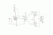
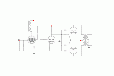
Needs some caps after the cathodyne for voltage isolation. Main problem will be the low and varying impedances seen by the cathodyne (due to driving the output stage cathodes) especially with the outputs operating in class AB.
With some Mosfet followers to drive the output stage cathodes inserted in between it could work.
With some Mosfet followers to drive the output stage cathodes inserted in between it could work.
Last edited:
Is Van Scoyoc the same as Blumlein garters?
No. The Van Scoyoc was an overly complicated phase splitter, and the Blumlein Garter circuit was a cathode biased arrangement that automatically balanced plate bias currents. Two different things.
The Van Scoyoc was an overly complicated phase splitter
I guess uoy refer to the cathode follower design
I believe it was done because of the need for a low impedance drive
from what I understand a trafo or interstage was originally used to 'drive' the Van Scoyoc splitter
the more complicated cathode follower design was implemented instead of the 'simpler' trafo
thats why I thought 'hey, cathodyne has low impedance too', right ?
but in my suggestion its the output stage that have cross referenced cathodes, and not the phase splitter
so it might be a completely different thing
but I don't know
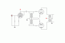
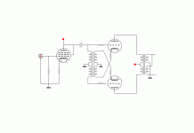
ok, different approach
transformer/autoformer used as phase splitter seem to become more popular
this one uses a relatively cheap interstage in a parafeed manner
and the secondary is used to cross reference output cathodes, in a kind of Van Scoyoc style
I suppose the IT is less critical this way
but is it possible ?
transformer/autoformer used as phase splitter seem to become more popular
this one uses a relatively cheap interstage in a parafeed manner
and the secondary is used to cross reference output cathodes, in a kind of Van Scoyoc style
I suppose the IT is less critical this way
but is it possible ?
Attachments
I guess uoy refer to the cathode follower design
I believe it was done because of the need for a low impedance drive
from what I understand a trafo or interstage was originally used to 'drive' the Van Scoyoc splitter
the more complicated cathode follower design was implemented instead of the 'simpler' trafo...
You have to consider the times when circuits such as the Van Scoyoc (and another one, the Isodyne) were developed. That was before the availability of decent solid state devices. There were no constant current ICs, no BJTs at all, and if there was anything, it would have been the noisy, unreliable, unstable point contact transistor.
They didn't have anything that could have served as a CCS for an actively loaded LTP. They were trying to solve problems that have much simpler solutions today.
Also, any time you have cross coupled feedback, you have a potential astable multivibrator.
The circuit in post 8 is looking better. The coupling xfmr needs to have a low output Z to drive the cathodes. And as Miles mentioned about cross coupled feedbacks turning into a multivibrator, the turns ratio for the low Z out xfmr would need to be low enough to keep the loop gain around the cross-coupled loop less than 1. Ie, the cathode currents must not excite their own grids with enough voltage to keep it oscillating. With the loop gain kept just below unity though, it may bootstrap the input impedance to eliminate loading on the 1st tube stage. Might be an interesting design concept.
I did notice the cross is missing the ground connection, by nature
and thought it might cause trouble, like you say
and, when reading about 'basics', I'm obviously 'forgetting' the ccs
which, like you say, makes a whole lot of difference getting good balance
thank you
google on LTP ccs, and a lot more to read
and thought it might cause trouble, like you say
and, when reading about 'basics', I'm obviously 'forgetting' the ccs
which, like you say, makes a whole lot of difference getting good balance
thank you
google on LTP ccs, and a lot more to read
The circuit in post 8 is looking better.............................With the loop gain kept just below unity though, it may bootstrap the input impedance to eliminate loading on the 1st tube stage. Might be an interesting design concept.
oh, ok, great
well, I also thought it looked better
I take it you would suggest something like 2:1 step down
"I take it you would suggest something like 2:1 step down"
Probably more. Lets say a 1 volt change on the output stage grid causes X mA of cathode current increase. (actually 2X for both output tubes together) Working that 2X current backward thru the xfmr from the cathodes to the load resistor for the input stage plate, this needs to produce less than 1 volt change there (and so on the output tube grids too). (or it will oscillate!)
Probably more. Lets say a 1 volt change on the output stage grid causes X mA of cathode current increase. (actually 2X for both output tubes together) Working that 2X current backward thru the xfmr from the cathodes to the load resistor for the input stage plate, this needs to produce less than 1 volt change there (and so on the output tube grids too). (or it will oscillate!)
Last edited:
"I take it you would suggest something like 2:1 step down"
Probably more.
well, the good thing is that the 'step down' doesn't affect the gain, as such...right ?
and primary impedance isn't so important as usual with IT....I guess ?
"well, the good thing is that the 'step down' doesn't affect the gain, as such...right ?"
The forward gain is affected a bit by the step-down ratio since it determines how much driver voltage change goes to the cathodes. But the driver plate to output grid voltage stays unity. So driver output transfer is (unity+step-down fraction) to the output stage. Ie, No big deal.
The forward gain is affected a bit by the step-down ratio since it determines how much driver voltage change goes to the cathodes. But the driver plate to output grid voltage stays unity. So driver output transfer is (unity+step-down fraction) to the output stage. Ie, No big deal.
- Status
- This old topic is closed. If you want to reopen this topic, contact a moderator using the "Report Post" button.
- Home
- Amplifiers
- Tubes / Valves
- My new humble thread


