First off i would like to introduce myself. my name is Alex and i live in the United States. I have had a fascination with tubes since i was a child and now that i am working towards my degree in electrical engineering i have built many tube guitar amps.
So i am in the process of building my own amp from scratch. I wan't to fix bias the pre amp tube (12AX7) and get a true class A design working.
So i want to make sure that i have all of this right so heres how im looking at it.
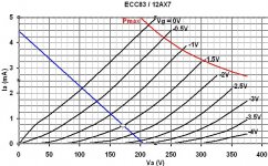
The maximum power this tube can dissipate is said to be 1 watt according to the datasheet. My input signal at a maximum will hit 3vpp and i do want distortion after 3vpp. Now since i want the bias to be centered and my input signal at a max will hit 3vpp, i need to bias the grid at -1.5v. Also i need as close to 0ma of current to flow when the grid voltage is at -3v so ill get clipping on the negative side of the input signal.
When the plate voltage is a 205vdc the graph show that 0ma of current will flow were the grid voltage is -3v. To get the current i will require for 1 watt of dissipation i divide 205 / 1 = 4.87ma.
So my load line will go between 4.9ma and 205v. to get the plate resistor value ill do 205 / .0049 and ill get 42kohms.
So the question is this, If i have a 12ax7 with all of these parameters, which as far as i can see is perfectly balanced for a 3vpp signal because it will clip after -3v and after 0v, is it setup properly for operation?
As far as desirable distortion goes in guitar amps, im pretty sure that most of it comes from some type of clipping and i need it to clip equally on the bottom (-3v) and top (0v) of the wave.
So i am in the process of building my own amp from scratch. I wan't to fix bias the pre amp tube (12AX7) and get a true class A design working.
An externally hosted image should be here but it was not working when we last tested it.
So i want to make sure that i have all of this right so heres how im looking at it.
The maximum power this tube can dissipate is said to be 1 watt according to the datasheet. My input signal at a maximum will hit 3vpp and i do want distortion after 3vpp. Now since i want the bias to be centered and my input signal at a max will hit 3vpp, i need to bias the grid at -1.5v. Also i need as close to 0ma of current to flow when the grid voltage is at -3v so ill get clipping on the negative side of the input signal.
When the plate voltage is a 205vdc the graph show that 0ma of current will flow were the grid voltage is -3v. To get the current i will require for 1 watt of dissipation i divide 205 / 1 = 4.87ma.
So my load line will go between 4.9ma and 205v. to get the plate resistor value ill do 205 / .0049 and ill get 42kohms.
So the question is this, If i have a 12ax7 with all of these parameters, which as far as i can see is perfectly balanced for a 3vpp signal because it will clip after -3v and after 0v, is it setup properly for operation?
As far as desirable distortion goes in guitar amps, im pretty sure that most of it comes from some type of clipping and i need it to clip equally on the bottom (-3v) and top (0v) of the wave.
You are unlikely to get equal clipping as you are relying on two quite different phenomena: valve cutoff (at -3V) and grid current (somewhere between -1V and 0V). There is no such thing as a perfect bias point, merely the optimum compromise given particular requirements. Bear in mind that the datasheet graphs don't tell you what any particular 12AX7 will do, but merely something like an average or typical response.
If you want carefully defined symmetrical clipping then you need to use a pair of biased diodes. In most cases this is not what you want in a guitar amp, but I will leave the rest to experts.
If you want carefully defined symmetrical clipping then you need to use a pair of biased diodes. In most cases this is not what you want in a guitar amp, but I will leave the rest to experts.
Well, if it is for the input stage of the amp. don't have to bias it that cold, almost all designs have them biased at -1.5 V. However, keep in mind that in 12AX7 grid current starts at around -0.5 to -0.9 V.
And do not obsess in minor changes from datasheet to application, it will still work fine. You 'd have to fcuk it up pretty bad to make it not work...
And do not obsess in minor changes from datasheet to application, it will still work fine. You 'd have to fcuk it up pretty bad to make it not work...
On my amps I like to have a couple clean stages, then a couple more to overdrive them.
So when the overdrive is on, I have four cascading stages before the phase inverter. (LTP)
This is with two 12ax7's.
I use 220K Rp on the first stage and 150K Rp on second, with 3K3 and 2K2 corresponding cathode resistors.
Plate voltage at the tube pins around 200v.'
That seems to give me a very nice clean sound and OD sound.
On my amps I like to have a couple clean stages, then a couple more to overdrive them.
So when the overdrive is on, I have four cascading stages before the phase inverter. (LTP)
This is with two 12ax7's.
I use 220K Rp on the first stage and 150K Rp on second, with 3K3 and 2K2 corresponding cathode resistors.
Plate voltage at the tube pins around 200v.'
That seems to give me a very nice clean sound and OD sound.
Question on tone: Since you run the 2 first stages clean and center biased, it seems it does not really matter if it's a 12AX7 or some other tube. right?
Why do you want symmetrical clipping? The best "sounding" clipping distortion for guitar usually is when it is unsymmetrical. And why just at 3V?
3vpp is typically the accepted value to start clipping, or 1.5vp. Secondly from what I've read / experimented with, asymmetrical clipping is raspy and edgy and sounds more like today's distortion pedals. Symmetrical clipping is more rounded and full and sounds more like 50s-70s tube amps that are being over driven or like tube screamer pedals.
On my amps I like to have a couple clean stages, then a couple more to overdrive them.
So when the overdrive is on, I have four cascading stages before the phase inverter. (LTP)
This is with two 12ax7's.
I use 220K Rp on the first stage and 150K Rp on second, with 3K3 and 2K2 corresponding cathode resistors.
Plate voltage at the tube pins around 200v.'
That seems to give me a very nice clean sound and OD sound.
I agree that 4 stages each with a gradual climb in gain instead of two with huge climbs in gain is probably much better as far as linear tube response goes (or as close to linear as possible)
Don't most class AB power tubes clip symmetrically? because if both tubes clip simultaneously then the signal is put together as symmetrically clipping?
Unless i'm wrong, isn't all overdrive or distortion in guitar amps caused by clipping? Maybe not hard clipping into sharp square waves, but more of flattening the peaks and valleys of the wave.
And also aren't the two phenomena i'm looking for called saturation and cutoff? At 0v all of the current from the cathode will go straight towards the plate because grid will no longer be repelling any electrons back. Sure some current will go to the grid but wont most go to the plate?
I know every tube is different and that all of these numbers will be skewed when this is operating in real life. But if my goal is to get distortion when the guitars signal is over 3vpp then do i have it biased right? From what i understand 3vpp is strumming a guitar pretty hard.
This is my first shot at building one from scratch, i understand how they work pretty well. I just want to build my own. I just want to be sure my logic is correct.
Hi Alex,
Someone here recently showed me this website for a guy who really studied distortion spectrum. Naturally, his perspective might not match yours or mine (he's after an Eric Clapton sound), but the information regarding distortion technique is really interesting. Read through his guitar amp projects.
Bob Richards Audio Index
..Todd
Last edited:
Hi Alex,
Someone here recently showed me this website for a guy who really studied distortion spectrum. Naturally, his perspective might not match yours or mine (he's after an Eric Clapton sound), but the information regarding distortion technique is really interesting. Read through his guitar amp projects.
Bob Richards Audio Index
..Todd
Thank you very much for this. it seems were both in seeking the same type of distortion (eric clapton style) Very interesting ideas in there.
Secondly from what I've read / experimented with, asymmetrical clipping is raspy and edgy and sounds more like today's distortion pedals.
Note asymmetrical working point generates more 2nd harmonic, and that is usually characterised as "round". You might have some other issues that makes it edgy.
By the way, in our production amps we don´t use triodes at all at the input. The input pentode/cascode is actually with our TULP circuit that lets us run them continously variable from triode to pentode characteristics. And with asymmetrical workingpoint, no sight of edgy, harsh sound
 .
.I think 3V p-p, for any real period of time is only going to come from very strong HB pickups. It's hard to measure a guitar input since the signal is so nasty on a scope. I think I've used a compressor to try to measure my SD '59 pickups and I think I get around 2V p-p. Turn the compressor off and strum hard and it's hard to quantify. I was never able to find good documented figures on this.
Normally you don't want the 1st stage to clip since it normally has no attenuation on it's input (other than the guitar's volume knob.) Many guitars need to be turned up all the way to avoid a change in the EQ you hear. If the 1st stage clips under a "default" setting on your guitar you will never be able to play the amp "clean" at any volume from the speaker. This only happened to me with one guitar. A Gibson LP with Dimarzio Super Distortion pickups. The volume on that guitar has to be down somewhat to avoid overdriving the (#1) inputs on my '71 Deluxe Reverb. This is why they also have the #2 input of course.
However, a bias in the middle of cutoff and saturation helps allow for "more cleans" than otherwise, so that spec target seem fine to me. Based on your 205 plate volts at cutoff (PS voltage at that node,) your plate resistor and middle bias target I get this from my load line excel file. The red line is 1watt which is not being reached. I don’t think guitar amp 12ax7s typically reach 1watt at any moment on the typical load line but I could be wrong of course.
Attachments
Hi Alex,
Someone here recently showed me this website for a guy who really studied distortion spectrum. Naturally, his perspective might not match yours or mine (he's after an Eric Clapton sound), but the information regarding distortion technique is really interesting. Read through his guitar amp projects.
Bob Richards Audio Index
..Todd
Hmmm...this doesn't start off well:
Bob is a bit confused here."My understanding of the musical relationshipsbetween the fundamental and its harmonic distortion products led me to realize that although I definitely don't want distortion products to extend way out in frequency from the fundamental (which feedback causes), the other really important thing is to have a dominant 2nd harmonic (same note as fundamental but one octave higher). The 2nd harmonic is also the first "even" harmonic. The 2nd harmonic seems to enhance anything. It seems always desireable.
The third harmonic is 1.5 octaves above the fundamental - it forms a major chord with the fundamental and/or the 2nd harmonic. That's an enhancement when the song is in a major key, but a likely a "dissonance" when the song is in a minor key, or any minor chord is employed.
Harmonics beyond the third are hit/miss as to whether they are pleasantly musically related to the fundamental. I found this out by playing the notes on a piano that were of the same frequency as each of the harmonics, along with the fundamental."
The third harmonic is not a musical major 3rd interval, but actually a "musical 5th". That is, it forms an open two-note chord, left undefined as "major" or "minor".
This is a typical confusion by amateur musicians/electronic experimenters.
The "musical 5th" (an interval of 5 notes in a major/minor scale, counting both the starting and ending note) is a mathematical '3rd', that is a multiple of 3 times the ROOT frequency of a 2-dimensional vibrating object like a string or column of air.
The "musical 3rd" (major 3rd) is actually the FIFTH harmonic, or a frequency 5 times that of the Root or fundamental vibration. It happens to fall upon a 'major 3rd' interval on a pure (untempered) musical scale, because it is an interval of 3 notes (counting start and finish), the notes actually being that of the 4th and 5th harmonics, not the interval between the Root and the harmonic, which would be two whole octaves plus a musical major 3rd.
The interposition of '3rd' and '5th' between harmonics and musical scales is a random coincidence based on conventional naming, and completely irrelevant (unless you have a New Age religion to base on it).
---------------
Moving along, Bob's uncontrolled experiments based on Rickard Berglund's 1995 observations probably have some significance, although Bob's understanding of higher harmonics and their musical contribution to tone amounts to unusable anecdoting.
The final quotation from Russell 0. Hamm's observations cannot be taken and applied, since it takes no account of the various effects of musical tempering of scales, and the difference for instance between the musical meaning of 'equal temperament' musical major 3rds, and actual major 3rds as played in string quartets and horn sections (entirely different musical languages).
A few decades of music theory would help Bob immensely here.
Last edited:
What you need really is my ideal Bias point chart:
This is the Bermuda Triangle of Tube Biasing:
(click to enlarge)
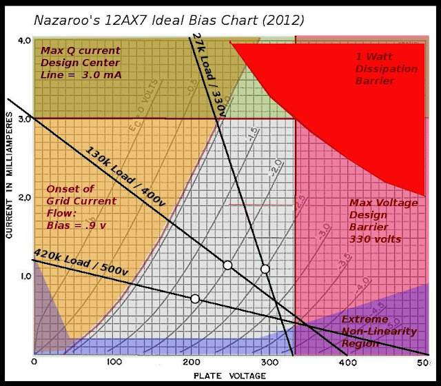
There is really no single ideal bias setup,
however, you can intelligently select operating points and ranges based on intended use.
Here are some examples:
(1) Hi-Fi setup: High Voltage B+ (500v) and Large Load (420k), to minimize distortion and maximize voltage transfer to load (this is not a power circuit, so voltage is more important than power transfer efficiency). Although higher voltages raise risks, they give more horizontal loadlines, which means current remains stable (think CCS). Headroom is not paramount here, because typical input signals will be played at low to mid-level volumes, to further limit system distortion, and protection against high voltage swings can be built in via -db pads for input of stage.
A lower bias point is selected, to better center swing in zone of maximum linearity.
(2) Universal Soldier Setup: Slightly Higher Voltage B+ (400 v range) Here is the mid-zone. Reasonable voltage and current excursion is expected, and more current can give both stability and a current source for subsequent stages which might need draw. a bias-point of -2v gives a nice centering for a balance of headroom and linearity.
(3) Guitar Maniac Setup: Here overloading is expected and harmonic distortion (non-linearity) is actually desired. Lower plate load gives a nice steep 'dive-bomb' loadline, while lower plate voltage (330 B+) protects tube from HV shorting, and allows pushing tube into cut-off safely. The higher bias point (-2.5 to even 3.5) is chosen to give maximum headroom for wild guitar antics and easy sliding into non-linear 'sweet-spots', without driving tube into grid-conduction, which is a non-musical type of distortion.
This is the Bermuda Triangle of Tube Biasing:
(click to enlarge)
There is really no single ideal bias setup,
however, you can intelligently select operating points and ranges based on intended use.
Here are some examples:
(1) Hi-Fi setup: High Voltage B+ (500v) and Large Load (420k), to minimize distortion and maximize voltage transfer to load (this is not a power circuit, so voltage is more important than power transfer efficiency). Although higher voltages raise risks, they give more horizontal loadlines, which means current remains stable (think CCS). Headroom is not paramount here, because typical input signals will be played at low to mid-level volumes, to further limit system distortion, and protection against high voltage swings can be built in via -db pads for input of stage.
A lower bias point is selected, to better center swing in zone of maximum linearity.
(2) Universal Soldier Setup: Slightly Higher Voltage B+ (400 v range) Here is the mid-zone. Reasonable voltage and current excursion is expected, and more current can give both stability and a current source for subsequent stages which might need draw. a bias-point of -2v gives a nice centering for a balance of headroom and linearity.
(3) Guitar Maniac Setup: Here overloading is expected and harmonic distortion (non-linearity) is actually desired. Lower plate load gives a nice steep 'dive-bomb' loadline, while lower plate voltage (330 B+) protects tube from HV shorting, and allows pushing tube into cut-off safely. The higher bias point (-2.5 to even 3.5) is chosen to give maximum headroom for wild guitar antics and easy sliding into non-linear 'sweet-spots', without driving tube into grid-conduction, which is a non-musical type of distortion.
Last edited:
One thing that many people will notice, is that a large number of circuits load and bias 12AX7s nowhere near the design-center Triangle depicted above.
It will be a good exercise in fact to take both your favorite circuits (and your notorious pet peeves) and put them on my chart, to see how and where they are screwing up.
As I maintained in another thread, few people know how to properly set up a tube for the intended purpose.
People should feel free to post their examples here, not for ridicule, but for analysis, and prediction of circuit behavior.
One thing to observe here is that:
(1) proper bias and setup is first dictated by intended use of the circuit. This must be nailed down first.
(2) Next, appropriate B+ voltages and loads are chosen, to fix the slope and position of the load line.
(3) Now, the bias-point is selected based on the balance desired between headroom/input range and non-linearity/harmonic distortion.
(4) To force the bias-point, the correct self-biasing cathode resistor is chosen, or better, several tubes are set up in a rig, and the resistor is selected by experiment to put the bias-point in the best compromise position between the acceptable range of tube samples.
(5) The performance of the circuit is tested under realistic conditions, including input signals, and output loads from following stages. Attenuation or amplification is adjusted at the input, and impedance matching is done at the output, to conform to expected conditions.
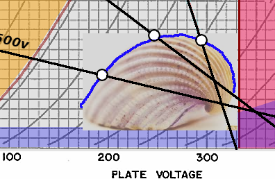
Finally, notice that the ideal bias-point slides along the load-line to the left, as the load-line tilts toward horizontal and slides to the right. The Bias Point traces the beautiful mathematical curve known as the sea-shell spiral:
(1) proper bias and setup is first dictated by intended use of the circuit. This must be nailed down first.
(2) Next, appropriate B+ voltages and loads are chosen, to fix the slope and position of the load line.
(3) Now, the bias-point is selected based on the balance desired between headroom/input range and non-linearity/harmonic distortion.
(4) To force the bias-point, the correct self-biasing cathode resistor is chosen, or better, several tubes are set up in a rig, and the resistor is selected by experiment to put the bias-point in the best compromise position between the acceptable range of tube samples.
(5) The performance of the circuit is tested under realistic conditions, including input signals, and output loads from following stages. Attenuation or amplification is adjusted at the input, and impedance matching is done at the output, to conform to expected conditions.
Finally, notice that the ideal bias-point slides along the load-line to the left, as the load-line tilts toward horizontal and slides to the right. The Bias Point traces the beautiful mathematical curve known as the sea-shell spiral:
- Status
- This old topic is closed. If you want to reopen this topic, contact a moderator using the "Report Post" button.
- Home
- Amplifiers
- Tubes / Valves
- 12ax7 perfect bias point