Maybe some of you old-timers will remember a series of modifications to the Dynaco PAS III preamp, featured in The Audio Amateur in the early 80's, by David Vorhis, entilted "The Last PAS."
David tried several different modifications to the preamp, most notably: 1) a better RIAA curve fit on the phono section; 2) elimination of the tone control section; 3) line stage re-design consisting of a common-cathode stage feeding a cathode follower, and 4) a regulated solid state power supply.
I liked the idea of the improved RIAA section and the regulated supply. I bought a bare phono section PCB and made the mods that David suggested.
I also bought a third party PS board and stuffed it.
The only thing that I didn't like about the "Last PAS" was the line stage. The first stage inverts the signal, and the 2nd stage is a 12AX7 based CF. The plate load of the 12AX7 is too high for driving cables and level controls.
I've been looking closely at John Broskie's "Aikido" CF designs, and in fact I bought some PCBs from him. The boards are great quality, but they are HUGE.
A clever and enterprising eBayer took Broskie's circuit and made it fit the size and hole pattern of the PAS III line stage. He sold me a stuffed board that I spec'd for 6CG7 tubes. Problem solved!
I'd post an eBay link, but I think that's against the rules, so just use this search term:
DYNACO PAS-2 PAS-3 AIKIDO UNITY GAIN BUFFER LINE AMP
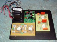
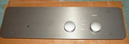
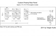
I bought a surplus case from eBay, that had a nice thick front panel, and a couple of silver knobs from China. I had a local sheet metal firm make the base, which you can see in the photo below. They will also be doing a custom rear panel.
In the layout, the phono section, shown on the right hand side of the photo, sits back from the front in order to allow room for the Alps level control, and the 3-way selector switch. The switch, BTW, is a great solution from Broskie, to the tune of $8.00 (including a PCB to make the wiring simple). I used some brass 6-32 stand-offs that I took from old PCs. I used a 6-32 tap for the holes,and so the stand-offs simply screw into place. I haven't drilled holes for the transformer yet.
Wiring from the selector switch to the input jacks on the rear panel will be bundled to the right of the phono PCB.
I eliminated the tube rectifier (for lack of space) and am using an off-the-shelf Hammond transformer for the B+ and filament supplies.
This is a simple, straight-forward approach for a tube preamp. It's not really a "PAS" preamp, except for the RIAA stage, which has been modified.
My issue with some PAS mods (e.g. Van Alstine Super PAS) is that by the time you get done putting the transformer on the outside, disconnecting the tone and other controls but leaving them in place, etc. you have created a bit of a Frankenstein. Also, the line amp has two 12AX7s in series (way too much gain) and the phono section drives the level and balance controls.
With the re-engineered 6CG7 Aikido stage, the phono stage is buffered by the CF, so there won't be any big load on the plates or consequential roll-off. The volume control comes after the CF, like a "passive pre." Well, sort of.
The nice thing is that the Aikido stage can be dropped into existing PAS amps for about $100, and it "solves" several issues, IMHO. I'm looking forward to hearing it.
I've got several projects going at once. I guess if you have to have a neurosis / mental illness / hobby, tubecraft isn't among the worst.
Jono
David tried several different modifications to the preamp, most notably: 1) a better RIAA curve fit on the phono section; 2) elimination of the tone control section; 3) line stage re-design consisting of a common-cathode stage feeding a cathode follower, and 4) a regulated solid state power supply.
I liked the idea of the improved RIAA section and the regulated supply. I bought a bare phono section PCB and made the mods that David suggested.
I also bought a third party PS board and stuffed it.
The only thing that I didn't like about the "Last PAS" was the line stage. The first stage inverts the signal, and the 2nd stage is a 12AX7 based CF. The plate load of the 12AX7 is too high for driving cables and level controls.
I've been looking closely at John Broskie's "Aikido" CF designs, and in fact I bought some PCBs from him. The boards are great quality, but they are HUGE.
A clever and enterprising eBayer took Broskie's circuit and made it fit the size and hole pattern of the PAS III line stage. He sold me a stuffed board that I spec'd for 6CG7 tubes. Problem solved!
I'd post an eBay link, but I think that's against the rules, so just use this search term:
DYNACO PAS-2 PAS-3 AIKIDO UNITY GAIN BUFFER LINE AMP
I bought a surplus case from eBay, that had a nice thick front panel, and a couple of silver knobs from China. I had a local sheet metal firm make the base, which you can see in the photo below. They will also be doing a custom rear panel.
In the layout, the phono section, shown on the right hand side of the photo, sits back from the front in order to allow room for the Alps level control, and the 3-way selector switch. The switch, BTW, is a great solution from Broskie, to the tune of $8.00 (including a PCB to make the wiring simple). I used some brass 6-32 stand-offs that I took from old PCs. I used a 6-32 tap for the holes,and so the stand-offs simply screw into place. I haven't drilled holes for the transformer yet.
Wiring from the selector switch to the input jacks on the rear panel will be bundled to the right of the phono PCB.
I eliminated the tube rectifier (for lack of space) and am using an off-the-shelf Hammond transformer for the B+ and filament supplies.
This is a simple, straight-forward approach for a tube preamp. It's not really a "PAS" preamp, except for the RIAA stage, which has been modified.
My issue with some PAS mods (e.g. Van Alstine Super PAS) is that by the time you get done putting the transformer on the outside, disconnecting the tone and other controls but leaving them in place, etc. you have created a bit of a Frankenstein. Also, the line amp has two 12AX7s in series (way too much gain) and the phono section drives the level and balance controls.
With the re-engineered 6CG7 Aikido stage, the phono stage is buffered by the CF, so there won't be any big load on the plates or consequential roll-off. The volume control comes after the CF, like a "passive pre." Well, sort of.
The nice thing is that the Aikido stage can be dropped into existing PAS amps for about $100, and it "solves" several issues, IMHO. I'm looking forward to hearing it.
I've got several projects going at once. I guess if you have to have a neurosis / mental illness / hobby, tubecraft isn't among the worst.
Jono
Attachments
Last edited:
There is PCB for Norman Koren mod
Classic Valve Design - Dynaco Clone and Original Design Boards and Repair Kits - Dynaco ST-70 Modifications
and for single tube line stage.
Classic Valve Design - Dynaco Clone and Original Design Boards and Repair Kits - Dynaco ST-70 Modifications
Classic Valve Design - Dynaco Clone and Original Design Boards and Repair Kits - Dynaco ST-70 Modifications
and for single tube line stage.
Classic Valve Design - Dynaco Clone and Original Design Boards and Repair Kits - Dynaco ST-70 Modifications
At one time, I had fit one of SYS's "Impasse" boards into a PAS chassis, but wasn't happy with the layout for the power supply. That PAS will probably become home to Joachin Gerhard's "Rabbit Hole" (described in Linear Audio Vol 0) when it's complete. (Fwiw, the Impasse is now in the chasis of a defunct Eico signal generator.)
If my memory is correct, the pass transistor in the LastPAS was hotting up. Here's a little article I wrote on it:
DIY Test Equipment for Audio and Ham Radio Enthusiasts
I would size R2 such that the resistor is doing most of the work, and the pass transistor less. Make sure you're getting enough base drive to the transistor as well. In my case, the pass transistor was an MJE3439 and it was heating up too much (or the heat sink was woefully inadequate.) The noise measurement isn't per root Hz as the analyzer used was an HP3581 with 3Hz bandwidth setting, not the AP I subsequently acquired.
- Status
- This old topic is closed. If you want to reopen this topic, contact a moderator using the "Report Post" button.