I have just finished a build of the line stage part of Allen Wright's FVP5A circuit and would appreciate some opinion as to the voltages I have measured.
Schematic is below. My PS is CLCRCRC with tweaked resistor values to get the desired 250V B+.
I am getting 160-170V on the anodes of the lower tube. Now this may be OK but my feeling is it's a bit high. What do you reckon?
Measured currents are about 3mA through the gain tube and 10 mA down the cathode follower bit.
Yes, too high. It should be about 102-105V. Disconnect the CF and see what plate voltage you get on the voltage amp. Adjust the cathode resistor to get 100V on the plate (like it says on the schematic), then hook the CF back up.
Alternatively, if you have a pile of ECC88-oids around, you can change the input tube until you find one that gives you the right plate voltage for that design.
Alternatively, if you have a pile of ECC88-oids around, you can change the input tube until you find one that gives you the right plate voltage for that design.
My creation of FVP5A
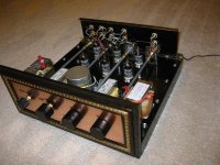
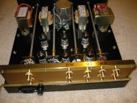
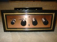
First off, the passing of Mr. Wright is sadly missed by everyone. I came across the discussions regarding the DIY of this excellent pre-amp. I like to share some pics of my humble creation. However, I have experienced some problem and will start trouble shooting tomorrow. I used it to drive my 2A3 SE power amp which has has a EM84 electronic eye as VU meter. Even if there is no signal to the phono, once in a while I find there is a sudden quick surge of signal and can be seen from the EM84 beam closing and at the same time I can see the cone of my 96db Fostex 206e moves. If LP is playing, it can be heard as a sudden "hiccup". It appears that the circuitry is not very stable and causes some sporadic oscillation. After reading the discussions, I noticed that the plate of the lower tube of the one I built also has about 170-180 v. if the B+ is 250v. Tomorrow I will attempt to adjust the 2K2 to get about 100-105v and see if this is the cause and report back.
Also I wonder If R1 should be 47K for mm cartridge instead of 100R as indicated in the schematic ? could it be a mis-print ?
Attachments
I don't understand SY's "disconnect the CF..." However, I have to decrease the 2K2 resistor to about 500-500R to get around 105-108V on the anode of the lower 6922. Because of this the B+ has dropped from 250V to only 215V. I hope it is still OK. For rectification I am using an isolated 110V/220V transformer - 4x FR205 diodes in bridge -> 40uf motor run cap-> 15H 70mA choke->100uf Mundorf electrolytic->100R 10W->100uf Mundorf. The sound is very good and the random "oscillation" or "signal surge" has disappeared. Any comments will be appreciated.
Disconnect the CF means disconnect the 100R resistor from the gain stage anode. This allows the gain stage to temporarily operate independently of the final "totem-pole" stage for adjustment that cathode resistor. I ended up with 430R, so we're in the same ballpark. Whether your B+ is now too low, I don't know. 10% either way is usually fine but you are outside that range.
There is a typo in the text below the schematic. It should be R2, on the FET source pin, that is 100R for MM. R1 is 47k for MM.
There is a typo in the text below the schematic. It should be R2, on the FET source pin, that is 100R for MM. R1 is 47k for MM.
By decreasing the 2K2 cathode resistor of the first stage you have increased the current draw considerably. This is not desirable and accounts for the sagging of your +B. You need to increase the load resistor to about 33K and see how your voltages settle down.
Surprisingly the amp will settle down to operate nicely whatever voltage is on the plate of the first stage - but the tone of the amp will vary quite substantially over a range of voltages. It maybe an idea to temporarily use a pot to set the voltage to whatever sounds best to your ears.
Shoog
Surprisingly the amp will settle down to operate nicely whatever voltage is on the plate of the first stage - but the tone of the amp will vary quite substantially over a range of voltages. It maybe an idea to temporarily use a pot to set the voltage to whatever sounds best to your ears.
Shoog
Thank you for your input rhone and Shoog.
I am getting 221v. after the 15H choke and 215v after the 100R cap. I will try to eliminate the 100R and the second 100uf Mundorf electrolytic and get the 221v right after the choke and see what happens. I know by eliminating the 100R and the 100 uf cap. I will compromise a bit on the DC smoothing, but it worth the try in order the get closer to the desired 250v B+ (within 10% as advised by rhone)
Shoog: Do you mean to increase the plate resistor of 25K to 33K ?
I have to do some traveling for a couple of weeks and I will report back after trying different tweaks after my return.
Thank you both again.
Thanks for your input, Shoog. I have recently been going back thru' the archives and enjoyed reading about your build of this excellent pre-amp. The way Allen has drawn the circuit we get 6 mA through that gain stage, do you think this is optimum?By decreasing the 2K2 cathode resistor of the first stage you have increased the current draw considerably. This is not desirable and accounts for the sagging of your +B. You need to increase the load resistor to about 33K and see how your voltages settle down.
Surprisingly the amp will settle down to operate nicely whatever voltage is on the plate of the first stage - but the tone of the amp will vary quite substantially over a range of voltages. It maybe an idea to temporarily use a pot to set the voltage to whatever sounds best to your ears.
Shoog
I know you experimented with various alternatives to the "plain vanilla" cathode resistor on that stage. What do you think worked out best?
Hello Shoog and Rhone,
As suggested, I have replaced the 25K plate resistor with 33K. The plate voltage (1st half of line stage 6922) has now dropped from 107Vdc to 90Vdc. I replaced the 2K2 with 750R (instead of 500R before) and getting 114-118Vdc. Obviously this has helped reducing the current draw from the B+. I am able to maintain the B+ @ 228Vdc (better than the 213Vdc before). The line stage seems more stable and no more sign of oscillation is observed. Any other suggestions would be appreciated.
Regards,
Ken
Hi Shoog,
a real stupid question:
Allen uses 25k wirewound, and he wants us to change the 2,2k that way, that we reach 100V, this corresponds to a specific current through the anode resistor. If I change this anode resister, would this no completely alter the harmonic spec of the preamp (In my opinion, the choice of the anode load is vital for the distortion...)
Regs, Dirk
P.S.: Another point: Lowering the cathode resistors from 2,2k to around 500 ohm meant 75% less local feedback, in the end: 4 times the amplification and 4 times distortion!!!
What I tended to do with mine was to place a wirewound pot on the last stage of the power supply, before the final cap, before feeding the input stage B+. This allowed me to tune the anode voltage into just the right voltage to give me the tone I wanted. A 1K resistor was all that I needed. This allowed a surprising amount of fine tuning to the overall tone - from fat to lean.
Shoog
Shoog
Thanks for your input, Shoog. I have recently been going back thru' the archives and enjoyed reading about your build of this excellent pre-amp. The way Allen has drawn the circuit we get 6 mA through that gain stage, do you think this is optimum?
I know you experimented with various alternatives to the "plain vanilla" cathode resistor on that stage. What do you think worked out best?
6mA would be about optimum in this situation. Anything more is going to shorten valve life quite a bit with almost no sonic gain. I have since built a new version using ECF80's which passes 10mA in both input and output stages - I think it sounds better than the ECC88 version - but that could be attributable to many other factors.
This is a very versatile circuit which can be made to work with any number of valves. I have always fancied building a version using a DHT in the front end. The 5687 seems like a much better fit for the input valve - lower gain and fuller sound.
Shoog
Given a bias point of -2.7V @ 0.006A (2.7/0.006) gives a cathode resistor of 450R.
You could use the 5687 as the Constant Current souce - but in my opinion it would be better to use each triode for each channel of the front end. Then use a single ECC88 for the bottom and middle of the SLCF, with the top been taken by another ECC88 with one triode for each channel.
The is absolutely no sonic benefit to keeping the two channels in different valve bottles as there will be no noticable cross talk.
Shoog
And to continue: You also have experience using fets for the slcf:
My idea is, using a cascoded bjt current source, and a mosfet for the upper part. Should I use 6h30 for the cathode follower (best current?)
I really don't understand, why a valve for the upper follower is a benefit...
Did you try with fet and valve in comparison??? Or did you try the fet for current source and upper follower, an then switch over to 6922 valve arrangement?
I highly appreciate your opinion, because I thing, you gained valuable experience...
Regs, Dirk
I like the 5687 a lot. Assuming a plate voltage of 100v and a desired plate current of 10mA gives a bias of -4V. This requires a cathode resistor of (4/0.010) 400R.
I never tried a transistor cathode CCSink in this design so can't comment on how it would sound. I did however use a pentode CCS in my ECF80 version and that worked out fine. I used a very simple screen regulator with a pot to vary the screen voltage and hence the current - this made it possible to set the current to exactly what I wanted using a simple adjustment.
I tried both a FET and a triode as the top element. I can't say as I heard a significant difference between the two - though I never did do any serious side by side listening. Allen always maintained that his thinking matured to go all triode with definate sonic benefits from doing so, and I am inclinded to say that he is probably right about that. The problem with FET's is always going to be large gate capacitance, which if not driven hard is going to effect the signal and introduce a "FET sound". Driving the gate capacitance as well as the output load is going to place more stress on the middle cathode follower element. There is also the small issue of reliability - FET's are not as robust as a valve. If you are going to use a FET consider a small signal JFET rather than a MOSFET.
On balance I would stick to an all valve version - but consider using a Pentode as the bottom element CCSink.
Shoog
- Status
- This old topic is closed. If you want to reopen this topic, contact a moderator using the "Report Post" button.
- Home
- Amplifiers
- Tubes / Valves
- Vacuum State FVP5A voltages