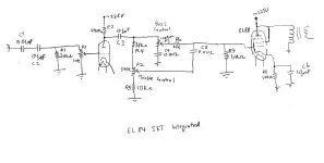
Does anyone see anything wrong with this schematic...??
This guy over at AA is trying to fix it for a friend. Problem is that is distorts heavily even at very very low volumes..
I told the guy that that it might be clipping because of the 89db speaker...but the very very low volume it should not clip..! Am I right, or am I right?
I noticed that the driver 12ax7 does not have a cathode resistor...but see no fixed bias...so would that be the problem..???
Here is what he mailed :
Anyway here is the schematics. Some correction though, the 12ax7 cathode is
connected to ground. The plate of the el84 is connected to the transformer
and not the B+. The other end of the transformer is connected to B+.
The pin9 of the EL84 is not connected to the plate directly but actually
goes through 1K/1W resistor and then to B+. I think it is configured as
Pentode mode
What I have done:
I have tap out from C3 output and make it as pre-out. Then I took the
pre-out and attached to my other amp. It produces nice sounding though some
clipping/distortion can be heard when the music is getting loud. I take it
as the driver is doing ok.
I am thinking on how to get to test the el84 now.
Attachments
Hi Bas. It looks to me like you need to do away with the input caps since most source components use an output cap these days. Also do away with R1. P1 will suffice there. In order to drop equal voltages across the plate resistor and the 12ax7 change the plate resistor to 220K and add a 2.4K cathode resistor. I would bypass the cathode resistor with a 100 uF cap also since you are going to lose a lot of gain in the filters following the gain stage. I would personally want a higher B+ on the 12ax7 as 225 volts doesn't leave a lot of room for biasing. The values I've given will only give about a -1.2 volt bias on the grid with about .5 mA though the tube. That's alot better than no bias though. HTH.
Hi Bas
Where did your friend get this circuit from? His grandad's radio? The net is full with working and sensible circuits, what's the need to use something dysfunctional?
Anyway, can't quite get how the EL84 is getting power - the primary of the transformer seems grounded.
peter
Where did your friend get this circuit from? His grandad's radio? The net is full with working and sensible circuits, what's the need to use something dysfunctional?
Anyway, can't quite get how the EL84 is getting power - the primary of the transformer seems grounded.
peter
Hi Peter. I think that Bas's friend made a correction on the EL84 in the email that he sent Bas.
" The plate of the el84 is connected to the transformer
and not the B+. The other end of the transformer is connected to B+"
Here is the statement I don't get:
"I have tap out from C3 output and make it as pre-out. Then I took the pre-out and attached to my other amp. It produces nice sounding though some clipping/distortion can be heard when the music is getting loud. I take it as the driver is doing ok"
I don't understand how he is getting anything but distortion if the schematic he sent is correct. My bet is that there is a cathode resistor but the input signal is making the stage clip. If the correction he made in the letter about the EL84 is true and the values given on the schematic are correct I doubt the output stage is the problem.
Hi,
The schematic isn't correct...Neither is his correction IMHO.
As EC8010 points out, for the EL84 you often have a 270R cathode R and about 270V B+.
It's "working" in pseudo triode mode as far as I can tell, not penthode.
This is one circuit in need of a complete redraw and it still wouldn't fit the speakers anyway.
Cheers,")
I don't understand how he is getting anything but distortion if the schematic he sent is correct.
The schematic isn't correct...Neither is his correction IMHO.
As EC8010 points out, for the EL84 you often have a 270R cathode R and about 270V B+.
It's "working" in pseudo triode mode as far as I can tell, not penthode.
This is one circuit in need of a complete redraw and it still wouldn't fit the speakers anyway.
Cheers,
"As EC8010 points out, for the EL84 you often have a 270R cathode R and about 270V B+"
That's true. They may have used one cathode resistor for both EL84 tubes though. I've seen SE EL84 amps from old magnavox consoles that used that arrangement. It does seem like a 120 ohm resistor would be better if that is the case. Those EL84's are running hot. As you said Frank, the schematic for the gain stage cannot be correct.
That's true. They may have used one cathode resistor for both EL84 tubes though. I've seen SE EL84 amps from old magnavox consoles that used that arrangement. It does seem like a 120 ohm resistor would be better if that is the case. Those EL84's are running hot. As you said Frank, the schematic for the gain stage cannot be correct.
I am the one!
Hi all,
To let you know that I am the guy who is trying to fix the problem of this amp. It does not belong to me but my uncle. This amp was built by his friend and he sold it to him.
The guy who built this amp did not interpret the electronics behind the circuit but simply build it based on memory that he got from an old amplifier many years ago. He never got around to modify it as he thought tube sound are supposed to be like that! Gosh! I pity this guy and helping my uncle to have a decent sounding.
I am very tempted to rip apart all the connection, leave the transformer tube and rebuild the whole amp.
I have tried a few of the tips mentioned in this post. Here is what I have done:
1. Remove all the caps at the input. Place a 47K at the grid.
2. I move the 500K potentiometer ( volume ) at the output of the 12ax7 after the capacitor coupling before the input stage of the el84.
3. Place a cathode resistor for the 12ax7 and a bypass caps.
4. Change the cathode resistor of el84 to 270ohm.
I am getting a slight improvement on the sound now but still the distortion exist but lesser noise background. But the distortion is still there at higher volume.
I am prepared to re-vamp the connection and break away from the design. Any contribution for schematics is very much welcome.
voltage values
Bournville,
You are right, I am having the volume control at the grid of the el84. I place a resistor ( 270K) at the grid of the 12ax7 and a 1M resistor at the input to the ground.
I was looking at the circuit from MUSICOM and some other circuit that places the volume control at the grid of el84. I realise the pot is much quieter in this configuration. Well... I can move it back to the grid of the 12ax7 if this is more advisable.
PRR,
The voltage values :
12ax7 grid : ( close to 0V DC)
12ax7 cathode: 2V
12ax7 B+: 304V
Cathode resistor : 1.5K
Cathode Caps : 0.68uF
EL84 grid1: ( close to 0V DC)
EL84 grid2: 304 V ( B+ for 12ax7 )
el84 cathode: 12.7V
el84 B+: 306V
Cathode resistor : 270
Cathode Caps : 10uF
Transformer:
Primary : 5K
Output : 4,8,16 ohm impedance.
Any other info that you need, please let me know.
Re: I am the one!
Good idea.
Reading your attempted improvements with the modifications, makes me wonder whether the output transformer is a SE type or a PP incorrectly used. The original builder's skill gives me no confidence.
A PP OPT will have 3 or 5 leads on the primary.
Before you go to rebuild it, is an EL84 in triode, which might give 1.5W enough power?
effindi said:I am very tempted to rip apart all the connection, leave the transformer tube and rebuild the whole amp.
Good idea.
I am getting a slight improvement on the sound now but still the distortion exist but lesser noise background. But the distortion is still there at higher volume.
I am prepared to re-vamp the connection and break away from the design. Any contribution for schematics is very much welcome.
Reading your attempted improvements with the modifications, makes me wonder whether the output transformer is a SE type or a PP incorrectly used. The original builder's skill gives me no confidence.
A PP OPT will have 3 or 5 leads on the primary.
Before you go to rebuild it, is an EL84 in triode, which might give 1.5W enough power?
Go for it!
Yes, start again. I fully agree with Brett. I'm afraid your original diagram provokes the thought, "If I was trying to go there, I wouldn't start from here."
effindi said:I am very tempted to rip apart all the connection, leave the transformer tube and rebuild the whole amp.
Yes, start again. I fully agree with Brett. I'm afraid your original diagram provokes the thought, "If I was trying to go there, I wouldn't start from here."
It's the plate resistor!
Hi all wonderful people of diyaudio.com!
I love this place. There are many generous knowledgable people. You helped a lot in trying to resolve this problem!
I was reading the posting of some of the thread here and one of the posting struck me!
The higher the plate resistor, the higher is the gain while a lower resistor yield a lower gain. Recommended value is 15K - 60K!
My plate resistor is 240K!
I change the resistor to 47K and bingo!
There was too much gain and the voltage swing at the el84 grid varies so much that it distorts/clipping easily! All the changes that I have done did reduce the current flow and improve the situation but the plate resistor is too large to resolve the problem.
Now it's time to clean up the connection... and some improvement.
I am also a little worry about the transformer.. I think it is meant for PP instead of SE. It have 3 leads at the input and the label indicates P1 - B - P2. Chances are it is a PP. Transformer is not cheap and if I am to live with it.. what harm will it do..?
Thanks to all...
> P1 - B - P2
That's a push-pull transformer.
> if I am to live with it.. what harm will it do..?
Used single-ended, the large unbalanced DC current will cause reduced bass response and increased bass distortion.
Also:
If you connect from P to B, the primary impedance is only 1.25K, mighty low.
If you connect from P to P, you get the 5K impedance which is about right, but the DC flowing through twice as many turns gives twice as much bass trouble.
Since this is a "small favor for an uncle", I am going to suggest the minimum changes to get reasonable performance. Of course if you decide to invest time and money, it is fairly clear how to keep the chassis and tube line-up (so as not to offend uncle's friend) while re-working the guts.
It should have a proper SE transformer but that's the most expensive part. Assuming you want to optimize the tranny you have:
Although your original schematic shows the EL84 working Triode, your voltage measurements suggest it is working Pentode. You can work a Pentode into a low impedance without gross distortion, just reduced power output. Unless this is a BIG transformer, I'd be inclined to keep it on the P-B 1.25K connection. I would also try (if you have the parts) a 0.005uFd 600V cap across the transformer primary to limit the rise in the treble caused by the utter lack of damping. (We can't do anything simple for the undamped rise at bass resonance: work Triode or rebuild it as a feedback amp.)
There is no feedback and a pentode amp without feedback is not a nice amp. Working Triode helps, but a triode with a very low load impedance isn't too nice either. I would try the P-P 5K connection and compare with the P-B 1.25K connection, see which sounds better.
With the fairly low load impedance, you could run more cathode current for more power. However more current will mean more bass shortage from DC saturation. You might try 180 ohm and 350 ohm EL84 cathode resistor, pick what gives good bass at low levels with the best balance of midrange and bass cleanliness at high level.
Both cathode caps are WAY too small for good bass response. The cheap-fix is to move the 10uFd cap to the 12AX7 cathode and get a 100uFd 25V-35V cap for the EL84 cathode.
240K may be a little high for the plate resistor on a 12AX7 with 1.5K cathode bias. But I would think it could swing the 12 volts needed here. 47K could be a little low for 12AX7; I'd try 100K. However if it is working, leave it alone.
That tone control scheme can't be "flat". It may not be bad, but you might want to try it bypassed before you worry too much about overall tone balance.
I sure would put the Volume control in front of the 12AX7, and a 0.1uFd cap in front of it to protect the amp from leaky sources (and to protect sources if this amp starts leaking DC out the 12AX7 grid). If that 2Meg resistor is still around, use it from 12AX7 grid to ground, so when the Volume pot wiper gets dirty the grid has a DC return. But if that's too much work, don't worry. Many grids returned only through pot wipers and survived.
- Status
- This old topic is closed. If you want to reopen this topic, contact a moderator using the "Report Post" button.
- Home
- Amplifiers
- Tubes / Valves
- Troubleshooting a single ended EL84