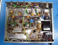
I need some help please. This Scott was in nice physical condition before I started working on it, but it had weak output, with the left channel being very low. Since it's of 1961 vintage, I decided to replace ALL the caps, whereas I used Nichicons for the power electrolytics (bypassing the cans) and Russian K40-9Y's in the audio path. The tubes tested good, but I installed a nos rectifier tube for good measure. I replaced 2 scratchy trimpots and AC and DC biases were peaked to spec. Every inch of the chassis was inspected for bad solder joints and good grounding. Pots and switches were Deox'd several times. The amp smoothly powered up and produced superb quality sound, which continued to improve over time. (~2 weeks). Then it began to hum. It was noticable at first with low or no input, but continued to get louder, being strongest on the phono input selection. The hum is even on both channels. I retested all the caps for esr, shorting and correct value and they were all fine. Now before I begin guessing on expensive parts replacement, how can I trace the source of this hum? Could it be the main xformer?
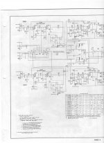
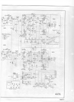
No I did not Frank. I have a schematic (see pics) and parts list, but didn't see anything resembling a bridge, except for the 5AR4 tube. Can you tell me where it's located in the chassis? And if not a rectifier, what else might be causing this annoying hum?
Attachments
My mistake. I just downloaded the original HH Scott schematic for the 222B.
It does not have a filament/bias bridge.
I own an HH Scott 299C and wrongly assumed that the 222 had a low voltage bridge like most of the HH Scott amplifiers.
When you replaced the original power supply caps, did you remove the originals?
What is the frequency of the hum? 60Hz or 120Hz?
It does not have a filament/bias bridge.
I own an HH Scott 299C and wrongly assumed that the 222 had a low voltage bridge like most of the HH Scott amplifiers.
When you replaced the original power supply caps, did you remove the originals?
What is the frequency of the hum? 60Hz or 120Hz?
60Hz. Could be a filament/cathode short on one of the tubes.
On my 299C, I installed a 1N4007 diode in series with each anode of the rectifier.
The diodes prevent damage if the 5AR4 develops a short.
I also added a 75 ohm resistor from each end of the 6.3 volt filament transformer winding to chassis ground. The resistors reduced the noise in my amplifier.
Are the B+ voltages normal?
Your preventative measures sound good and I may take your example. However, damage may have already been done. The B+ voltage is 363V at the rectifier. Spec is 380V, so I believe we're OK there. The service manual states that if a hum develops and increases, the power tubes may be gassy and should be replaced. Aside from the rectifier, are the power tubes the 12AX7's? I don't have any spares or quick access to a tube tester (hey, I'm a microelectronics guy) so I want to explore other potential causes before replacing them. Please note that this hum is negligable at normal listening levels on all but the phono selector.
The old HH Scott gear was very well designed. I listen to my 299C every day.
I'm a bit concerned that your B+ voltage is 363. The original spec was 380 with 117 volts on the transformer primary. If your line voltage is closer to 125 volts (as is normal today), the B+ voltage should be somewhat higher than 380 volts.
Something may be drawing too much current and causing the hum.
Fortunately, 6BQ5 tubes aren't too expensive. Antique Electronic Supply is a good place to start.
If you check the voltage with the tubes removed, it will be higher than normal.
The published specs are with the tubes in and operating properly.
My 5AR4 mod is easy to make. Pins 3 and 7 are not used. Move the transformer wire from pin 4 to pin 3. Install a diode between pin 4 and pin 3 with the cathode of the diode connected to pin 4. Move the transformer wire from pin 6 to pin 7. Install a diode between pin 6 and pin 7 with the cathode of the diode connected to pin 6.
This will ease the load on the rectifier tube as it is only passing d.c. It will extend the life of the tube many times over.
If you are hearing the 60Hz hum in both channels, it may or may not be the tubes.
I would expect 120Hz hum. With low B+ voltage and 60Hz hum, I would suspect a bad 5AR4 tube. Perhaps one of the rectifier sections isn't doing it's job.
You can temporarily replace the tube with a 5U4, 5V4, 5Y3 to see if the hum goes away.
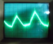
I'd definitely try another rectifier tube since it is 60Hz and the waveform looks like a filtered sawtooth. Scope the B+ carefully and observe whether you have 120Hz ripple or 60Hz, and the amplitude of that ripple at the first filter cap in the chain should be no more than a couple of volts p-p typically.. (More than 10V might be a cause of concern)
Adding UF4007 or 1N4007 in series with the plates of your 5AR4 rectifier is an excellent idea, been doing that for about 20yrs now, and will prevent damage to the rectifier in the event of brief interruptions in line voltage or someone turning the amp off and right back on without some wait..
The output tubes are 6BQ5/EL84, the driver tubes ECF80/6BL8, and the pre-amp tubes are 12AX7... Might want to pick up Morgan Jone's "Designing Valve Amplifiers, 3rd Edition" as this will help you to understand how your amplifier actually works.
When troubleshooting the amplifier use extreme caution - if you have not done so already please read the safety thread. Also always place a resistive load across the amplifier outputs when working on the amp powered up.. 8 Ohm power resistors are cheaply available at RS and other places.
Hi Kevin. Looks like you may be nearby. I've been doing repairs for about a year for a gentleman that deals in vintage audio. I've been on another side of electronics for many years, (Micro-circuit and PCB design) so this stuff is fairly new to me and I really appreciate your advice. AS I mentioned to Frank, I'm still seeing 60Hz, even with the 5U4 installed. I'll do the remaining tests soon and report my findings. Thanks again.
Ken
Ken
Hi Kevin. Looks like you may be nearby.<Snip>
Ken
Guests are always welcome around here, ping me sometime..

I put in a 5U4G and there's no change.
I remeasured the him and it is 60Hz.
What can I look at next?
Thanks for the protection advice. I'll install it before returning the amp.
I'm assuming this was hum on the output of the amplifier, you need to take a look at the power supply and make sure the ripple there is reasonable and 120Hz..
The next thing to suspect is probably a bad tube, is the problem more pronounced on one channel than the other? I remember you mentioning that the hum was worst on the phono stage? Have you tried shorting the phono inputs and making sure that in fact the 60Hz hum you are hearing is internal to the amp? No nearby fluorescent lamps with electronic ballasts? Anything change in the vicinity of the amp?
OK fellas...I misread my scope, sorry. The hum is 120Hz, not 60. I pulled the reading from the first power supply filter cap. 120Hz/1.6V p/p. The sinewaves are uneven.
I also shorted each phono input and the hum didn't change.
Changing its environment (fans, lights, placement, etc.) had nil effect.
The hum is even on both channels.
Are these valuable clues?
I also shorted each phono input and the hum didn't change.
Changing its environment (fans, lights, placement, etc.) had nil effect.
The hum is even on both channels.
Are these valuable clues?
I'm beginning to wonder if the problem is the power transformer.
If you measure the a.c. voltage to chassis ground from each anode of the rectifier tube, they should be nearly the same. If they're not the same, it might indicate some shorted turns on one side of the B+ secondary.
If you measure the a.c. voltage to chassis ground from each anode of the rectifier tube, they should be nearly the same. If they're not the same, it might indicate some shorted turns on one side of the B+ secondary.
I'm beginning to wonder if the problem is the power transformer.
If you measure the a.c. voltage to chassis ground from each anode of the rectifier tube, they should be nearly the same. If they're not the same, it might indicate some shorted turns on one side of the B+ secondary.
Good advice, they should match to within a couple of hundred mV or better typically..
The filament supply to the phono stage in this design is derived from the output stage cathode bias so the next step would be to verify that there is not excessive ripple present there. The relatively high dvdt of ripple waveforms may electro-statically couple to nearby circuit components in the phono stage as well as through the cathodes themselves. Ripple on this supply should low, at the phono tubes more than a few mV may be enough to cause an issue. I'd replace the electrolytics (25uF and 50uF) if you have not done so already.. Use the next larger commercially available values if you can't get the exact values stipulated. (Mouser and Digikey do stock some odd values made by Vishay and others so it might not be an issue.)
That's quite a bit of difference from the two ends of the B+ winding. They should be very nearly the same.
You may have a bad power transformer. If so, it will only get worse.
All may not be lost. I purchased an exact replacement transformer for my 299C from Heyboer Transformers. The price was very reasonable.
The model of my replacement transformer is HTS-4831-1.
It's not the same transformer as yours but they may have a replacement power transformer for your amplifier. Google Heyboer. I believe that it's http://www.heyboertransformers.com/
Last edited:
- Status
- This old topic is closed. If you want to reopen this topic, contact a moderator using the "Report Post" button.
- Home
- Amplifiers
- Tubes / Valves
- Scott 222B Hum