I feel like I should preface this post with long time listener first time caller or something like that. I'm not completely sure if I am posting this in the correct place but hopefully the mods will steer me to the right place if I am wrong.
I am in the process of planning out a a nixie clock, vacuum tube AM/FM radio. I have everything planned out for the clock portion and a few ideas for the radio but since the only tube radio I ever attempted was a single valve crystal radio that I built with my dad for a project in middle school many years ago, I am looking for some good sources for info and design ideas. I recently acquired a copy of the radiotron designer's handbook 4th ed. which has been quite helpful so far but I was hoping to get some additional info/schematics of projects people have attemped for Superhet AM/FM receivers.
I am in the process of planning out a a nixie clock, vacuum tube AM/FM radio. I have everything planned out for the clock portion and a few ideas for the radio but since the only tube radio I ever attempted was a single valve crystal radio that I built with my dad for a project in middle school many years ago, I am looking for some good sources for info and design ideas. I recently acquired a copy of the radiotron designer's handbook 4th ed. which has been quite helpful so far but I was hoping to get some additional info/schematics of projects people have attemped for Superhet AM/FM receivers.
Best to learn with a TRF radio, then try an AM superhet. To get any further you will need test equipment and experience. Don't try to start with an AM/FM set as you are almost certain to be disappointed. To be blunt, most audio people would struggle to correctly adjust an already-built FM set so building from scratch is harder.
I am not trying to put you off, just alerting you to the fact that you have started on a long and interesting journey. RF is harder than audio. VHF is harder than RF.
I am not trying to put you off, just alerting you to the fact that you have started on a long and interesting journey. RF is harder than audio. VHF is harder than RF.
Yeah, I fix amps, organs, preamps, mixers, but I can't get any sensitivity out of my dyna FM3 tuner yet. The schematics and alignment instructions are free now after 45 years, downloaded them last spring. Might work up to trying replacing electrolytic caps and aligning it next winter. I re-capped a buzzy hizzy, poor sensitivity 5 band (1979?) transistor radio last year, sounds great, super sensitivity on FM band. Only a mono radio, though, next act, stereo! (?)
To ease into radio, try repairing an old radio found at a charity resale shop. After that, buy some old Sams schematics or something, try to dupe the good ideas off one of those. Hard to buy the inductors and variable caps these days, easier to find them in old junk.
To ease into radio, try repairing an old radio found at a charity resale shop. After that, buy some old Sams schematics or something, try to dupe the good ideas off one of those. Hard to buy the inductors and variable caps these days, easier to find them in old junk.
Last edited:
Thank you for your thoughts. let me give you a bit of my background. I have a well equiped home office with plenty of test equipment so I should be fine there. I am an electrical engineer with a lot of experience in modern analog and RF IC design. I am well aware that I am in for a long project so that is not my worry. In fact, the fact that it is certainly not going to be a 1 weekend project and it is outside of my existing knowledge base is part of the appeal. in the process I will likely go through several iterations and most likely will start with a TRF module since this will give me something to learn the intricacies of tuning these types of radios.Best to learn with a TRF radio, then try an AM superhet. To get any further you will need test equipment and experience. Don't try to start with an AM/FM set as you are almost certain to be disappointed. To be blunt, most audio people would struggle to correctly adjust an already-built FM set so building from scratch is harder.
I am not trying to put you off, just alerting you to the fact that you have started on a long and interesting journey. RF is harder than audio. VHF is harder than RF.
OK, in your case the journey may be quicker! Much of what you already know will be directly applicable. Something which might catch you out is that stage gain for valve RF circuits is much greater than solid state, so stability can be an issue. Also, impedances are higher so stray capacitance tends to be a bigger problem than stray inductance.
I suppose what I am trying to say is that the theory you know is still true, but your experience could sometimes mislead you because valves are different.
I suppose what I am trying to say is that the theory you know is still true, but your experience could sometimes mislead you because valves are different.
I suppose what I am trying to say is that the theory you know is still true, but your experience could sometimes mislead you because valves are different.
you just hit the nail on the head for my biggest concern. Fortunately for my career, we dont have to worry about many of the same things RF designers did back then. Unfortunately for this project, I have never had to consider some of the same things I will now.
Yeah, I fix amps, organs, preamps, mixers, but I can't get any sensitivity out of my dyna FM3 tuner yet. The schematics and alignment instructions are free now after 45 years, downloaded them last spring. Might work up to trying replacing electrolytic caps and aligning it next winter. I re-capped a buzzy hizzy, poor sensitivity 5 band (1979?) transistor radio last year, sounds great, super sensitivity on FM band. Only a mono radio, though, next act, stereo! (?)
To ease into radio, try repairing an old radio found at a charity resale shop. After that, buy some old Sams schematics or something, try to dupe the good ideas off one of those. Hard to buy the inductors and variable caps these days, easier to find them in old junk.
Thanks for the tip on the dyna FM3. I found a link for the schematics here.
mcwilcr,
There are a couple of major stumbling blocks in your path towards building tubed superhet circuitry: acquisition of tuning capacitors and acquisition of IF transformers. IIRC, a fellow in Germany makes and sells IF trafos and you may be able to use reverse connected BJT trafos in a parafeed setup. Given your EE background, you may be able to solve the problem of using varicap diodes for tuning a tubed setup. If you do, PLEASE post your results here.
A simple AM project is a single tube regenerative setup. Only a readily available 365 pF. single gang tuning cap. is necessary and you get reasonable sensitivity.
A "slick" single bottle (12AT7/ECC81) FM design can be found here.
"Fine Wood Consoles" show up on the craigslist free and furniture list all the time- also $25 at the salvation army etc. Burn the fine wood, pitch the 3 gram ceramic cartridge phono player and tiny speakers, keep the radio for the inductors and capacitors. Why buy new? this stuff goes to the dump every day. Gets you some tubes and power transformers, too. New production 10.7 mhz and 655 khz mixer inductors are strange and rare. Don't know why- the all digital 2006 Sony pocket radio I bought when I dropped the GE pocket radio I had been using for a tuner, has all the sensitivity of a crystal set.You can find cheap AM/FM stereo receiver chassis cheap enough on e-pay, something from a vintage console, and modernize it using better parts than were available to original manufacturing. Anyway you will need to find at least cores for RF coils and IF transformers.
Last edited:
All radios are cheaply made using ceramic filters instead of IF cans and FM ones don't even have any tuned IF. I think a good crystal set is a lot better! This includes cell phones! I built a lot of radios in my life and they are full of tuned circuits, and very sensitive and have excellent selectivity. But who cares any more with the crappy stuff they broadcast today? MP3 has taken over.
All radios are cheaply made using ceramic filters instead of IF cans and FM ones don't even have any tuned IF. I think a good crystal set is a lot better! This includes cell phones!
I guarantee you that every decent radio sold today has tuned circuits and a tuned IF. The IF may use ceramic or crystal filters, and/or some digital filtering in the processor. If you were to sweep the passband of all but the cheapest of radios you would find selectivity better than anything with tuned LC filters inside.
Every cell phone made has to meet some pretty severe selectivity and intermodulation specs just to reject the unwanted signals on the neighboring channels. There is usually one or more SAW filters in the RF stages followed by a crystal or SAW in the IF and some serious DSP filtering in the baseband path. There are just too many people talking and texting away at the same time.....to quote an old rock song.....gotta keep em seperated!
I have worked for Motorola for nearly 40 years and I have designed a few cell phones and two way radios.
10.7 MHz ceramic filters for FM radio and 455 KHz filters for AM are still available in the Mouser and Digikey catalogs. They are low impedance devices (about 330 ohms) which would require some tricky impedance matching to use with vacuum tubes, but it could be done. Maybe a tube voltage amplifier paired with a mosfet follower for driving the low impedance.
The FM RF front end tank can be varactor tuned, and I am guessing you could find a rectifier diode that could be used to tune the AM band.
You could also up convert the AM band to the same 10.7 MHz IF used for AM thus simplifying the AM front end The LO would only need to tune 11.2 to 12.4 MHz, easilly done with a varactor. Narrow 10.7 MHz crystal filters for FM two way radio are available and have the right bandwidth for AM IF.
A doable project, but I would be tempted to cheat and use tubes for the audio, nixies for the frequency display, and hide a receiver chip under the deck somewhere.....
Oh, no one has asked the obvious......do you want FM stereo? If so read up on multiplex decoding. Those coils ARE hard to find.
You will need to give some thought towards the clock too. A digital clock, especially using a Nixie display could give you a problem with noise or interference from the clocks divider circuits. Nixie tubes in this application would be better run from a clean DC voltage rather than the once common practice of using a small switched inverter. It can all be done of course but you don't want to pick up 'birdies' all over the place due to poor screening etc.
I agree on the commercial and Ham radio stuff, but the AM and FM consumer stuff is a joke. Yes, way too many people with cell phones. I lived most of my life without one and still seldom use it. For emergencies, and usually doesn't work if more than 10 miles from a tower if lucky.
Varactors were common years ago, but can find them if you search. Or just get a bunch of car radios and salvage them.
A good AM IF bandwidth is 20 KHz, and 200 KHz for FM. I tried making 10.7 MHz crystal filter with 200 KHz bandwidth and I would say it can't be done using discrete crystals.
A good easy to use stereo decoder is LM1310. Only one adjustment pot.
Switched inverters have to be put in metal shield cans with feedthrough caps and filter coils. I have done it, but easier to wind a mains transformer for the Nixie voltages.
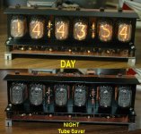
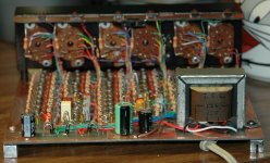
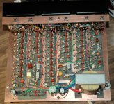
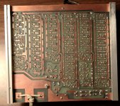
no radio but I built this from a kit and it is quite a conversation piece.
Hand built chassis - some oak boards and a hammond top plate.
It does have an alarm though.
My Nixie Tube Clock
Hand built chassis - some oak boards and a hammond top plate.
It does have an alarm though.
My Nixie Tube Clock
")
One great source of schematics and often also alignment information for existing, tube radios is Nostalgia Air
With diligent effort, one can find multigang tuning capacitors meant for AM/FM in surplus sites. Same with conventional IF transformers. Can't recollect exactly where, sorry, but google making your own IF transformers. With scrounged old fashioned cans and your own innards, you can make anything you want and reasonably easily.
George is very right about ceramic resonators. Might even be able to use them together with a 6BN6 as the FM demodulator, which would avoid the need for some sort of balanced IF transformer for either a Foster/Seely or a ratio detector.
As someone else asked, please post what you decide to build, should be VERY interesting!
- Status
- This old topic is closed. If you want to reopen this topic, contact a moderator using the "Report Post" button.
- Home
- Amplifiers
- Tubes / Valves
- Vacuum tube clock radio