Hi
I need some advice, and this is, without doubt, the best the place to get it! I’m confident where triode’s are concerned, but know only the basics when it comes to pentodes")
My friend’s 300B SE amp’s developed a fault, and I offered not only to repair but to upgrade them. As part of this process, I decided to try the pentode driver stage from the Legacy amp, shown below. I used a 6P15 (which is I believe, a SV83 in disguise!). The HT in the amp is 475 V. I decided to stick slavishly to the operating conditions shown, and so introduced a simple RC network to drop the driver’s HT to 420 V, to avoid exceeding the plate voltage rating of the valve. But, as the power supply in the amp is unregulated, I decided to use a regulator to put 160 V on g2 (this is functioning correctly). But the circuit didn’t operate as shown. I had to lower the cathode resistor to 240R to increase the current and thus lower the plate voltage to 270 V. The article I got the circuit from- writen by Thorsten Loesch- also talks of the driver running at 16 mA- which would have the 12k plate load resistor contravening Ohm’s law for a start….
As Mr Loesch has forgotten more than I know, I can only think that he drew the circuit to operate with a different pentode. Did I do the right thing to lower the cathode resistor in value? Would an alternative set of operating conditions be preferable? Any suggestions would be much appreciated.
Thanks
Paul Needs
I need some advice, and this is, without doubt, the best the place to get it! I’m confident where triode’s are concerned, but know only the basics when it comes to pentodes
My friend’s 300B SE amp’s developed a fault, and I offered not only to repair but to upgrade them. As part of this process, I decided to try the pentode driver stage from the Legacy amp, shown below. I used a 6P15 (which is I believe, a SV83 in disguise!). The HT in the amp is 475 V. I decided to stick slavishly to the operating conditions shown, and so introduced a simple RC network to drop the driver’s HT to 420 V, to avoid exceeding the plate voltage rating of the valve. But, as the power supply in the amp is unregulated, I decided to use a regulator to put 160 V on g2 (this is functioning correctly). But the circuit didn’t operate as shown. I had to lower the cathode resistor to 240R to increase the current and thus lower the plate voltage to 270 V. The article I got the circuit from- writen by Thorsten Loesch- also talks of the driver running at 16 mA- which would have the 12k plate load resistor contravening Ohm’s law for a start….
As Mr Loesch has forgotten more than I know, I can only think that he drew the circuit to operate with a different pentode. Did I do the right thing to lower the cathode resistor in value? Would an alternative set of operating conditions be preferable? Any suggestions would be much appreciated.
Thanks
Paul Needs
Attachments
http://www.diyaudio.com/forums/tubes-valves/137330-sv83-vs-el84.html
"SV83 is identical in construction to the 6p14p (which is equivalent to EL84)."
Russian 6P15P-EV = EL84/6BQ5 ??
"The 6p14pev is a drop in replacement for the EL84/7189, the 6p15pev is not(but close)."
6P15P, 6P15P-V, 6P15P-EV
Tube Tester Files - 6Ï15Ï - 6Pi15Pi (SV83)
"SV83 is identical in construction to the 6p14p (which is equivalent to EL84)."
Russian 6P15P-EV = EL84/6BQ5 ??
"The 6p14pev is a drop in replacement for the EL84/7189, the 6p15pev is not(but close)."
6P15P, 6P15P-V, 6P15P-EV
Tube Tester Files - 6Ï15Ï - 6Pi15Pi (SV83)
Hi euro21
I'd read about this, and opinions differ, but I thought that SV83 was a 6P15P, and 6P15P had identical characteristics to 6P14P, and that the only difference was that in 6P14P g3 was internally connected to the cathode, but in 6P15P it was not, and that 6P15P had an internal screen connected to g3, which was connected in turn to pins 1 and 6 (not connected in 6P14P). So the two valves were interchangable so long as one connected pins 1 and 6 of the valve base together. Am I wrong? I just checked the characteristics I have for both types, but they were measured at widely differing g2 voltages
Paul
6P14P and 6P15P produce different plate curves on a curve tracer. Thus, they are not the same.
See the attached file in the first post for plate curves, or check the data sheets:
http://www.diyaudio.com/forums/tubes-valves/187386-6p43p-strange-plate-graphs.html
See the attached file in the first post for plate curves, or check the data sheets:
http://www.diyaudio.com/forums/tubes-valves/187386-6p43p-strange-plate-graphs.html
Hi Yves
That looks about right as 240R is giving a plate current of 12.5mA. But if I drop the cathode R a litle to set 16 mA, the plate will fall to ~ 230 V.
Hi euro 21
Just took afternoon off to try a 6P14 (see the power you have over strangers?!) With a cathode R of 240R the plate drops to 200 V, with 211 V across the plate resistor so plate current has risen to 17.6 mA. Clearly I was wrong about the the equivalence of 6P14P and 6P15P!
But my original point remains. I could use a suitable piece of wet string to set the current through the plate resistor at 16 mA, but 16 mA through 12 k would still drop 192 V, putting the plate at 228 V, not 270 V, for an HT of 420 V!
And if the SV83 is an equivalent of either valve, it must be the 6P15P- as it has an internal screen and no internal g3 to k connection
So- should I drop the value of the cathode resistor to give 16 mA plate current, and live with predicted plate V of 230 V; or
fit a 6P14P, increase the cathode R to 470R, and hope for, and live with, 16 mA/plate 230 V; or
never agree to do favours for friends!
Thanks
Paul
Hi Gimp
I had thought it was always the plate current that was quoted in these characteristics, not the cathode current! Anyway, in my circuit with a 6P15P and 240R cathode resistor the cathode current is about 14.3 mA- so 1.8 mA g2 current. So I suppose it's more than possible that the plate current of a 6P14P with a 470 R cathode resistor might be 12.5 mA, with a g2 current of 3.5 mA
So is this the consensus- a SV83 has a screen and no internal g3-k connection, like a 6P15P, but has characteristics close to a 6P14P?
I will of course be trying a 6P14P with a 470R cathode resistor- soon
Thanks
Paul
I built the legacy driver stage. I recalculated the plate load and bias resistors. I am using a lower B+ with a 10k plate load but running a higher current. I find I can interchange both 6p14p and 6p15p in this setup as the higher bias current pushes both into a similarly linear portion of the curves.
This would be my choice. . .
So- should I drop the value of the cathode resistor to give 16 mA plate current, and live with predicted plate V of 230 V;
. . .
I routinely use pentodes with higher transconductance:

Yves.
Hi Paul, Don't worry, the pentode driver stage for 300B is easy to get working well - and sounds very good too.
First the SV83. Yes this was a **version** of the 6П15П. The 6П14П was never labelled SV83. There is some confusion around the 6П15П, as some versions (the OREL perhaps) used the same internals as a 6П14П, whereas others used a more sensitive G2.
In any event, I would never connect anything like 400V + to the anode of the 6П15П, not least because many are gassy now. I have arced them over at much less than this even with low VG2.
The 6П14П on the other hand, if made by Reflektor (most are) likes high voltage very much. If you use a 15K anode resistor, you can start with well over 400V, and this is a good idea, since the linearity improves with high current. Only trouble is that the cathode resistor value varies all over the place, and often needs trial & error to find.
Good idea to regulate the HT to this stage - the sound improves a great deal as the supply is cleaned up.
O, and IF pentodes, Like Yves' EF183, sound even better IME.
I have had excellent results with the EF80 and 6BW7, operating with an HT of 435V, 10mA, and about 20K of anode load [all from memory]. There's lots of variants of these around, and they are more linear than a 6П14П running 17mA, because 10mA is the ideal design-in working anode current for the EF80-class valves.
Another nice feature of these IF units is the bias - about 1,2V. You can slide in 1x IR LED in place of the cathode resistor, and compare the sound.
Then, when you get the itch to adjust it some more, you can triode connect them and run them in a shunt cascode, which ups the performance even further [and the gain to 250+]
Do you have a drawing for that "shunt cascode" ?. . . Then, when you get the itch to adjust it some more, you can triode connect them and run them in a shunt cascode, which ups the performance even further [and the gain to 250+]
I imagine that tubes are in serie for the signal but in parallel for the PSU, right ? ?
TNX2U
http://www.diyaudio.com/forums/tubes-valves/137330-sv83-vs-el84.html
"SV83 is identical in construction to the 6p14p (which is equivalent to EL84)."
Russian 6P15P-EV = EL84/6BQ5 ??
"The 6p14pev is a drop in replacement for the EL84/7189, the 6p15pev is not(but close)."
6P15P, 6P15P-V, 6P15P-EV
Tube Tester Files - 6Ï15Ï - 6Pi15Pi (SV83)
Scanned pages with useful graphs, from a great book:
www.wavebourn.com • View topic - 6p14p, 6p15p - what is difference?
Do you have a drawing for that "shunt cascode" ?
I imagine that tubes are in serie for the signal but in parallel for the PSU, right ? ?
TNX2U
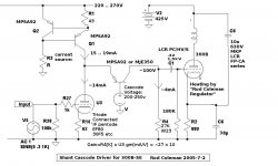
Salut Yves, Here is the shunt cascode driver.
The PNP Q2 fixes the anode voltage [to the peak voltage needed by 300B grid - 200 .. 250V].
The "overflow" current flows through R4 to give a class A voltage of ~100V.
The current source can be made with depletion FETs if you have them. If you use BJTs, take care for stability (ferrite beads useful!)
Gain = Gm x R4, so you can easily get x250 with IF pentode. R4 should be vitreous enamel [Welwyn W24 cheap and good]
Notice how the input and the output are both referenced to Ground, so you get excellent PS rejection, and excellent EMI protection.
Works with cheap series-heated pentodes like Mazda 6F23.
And the sound, IMO, is better than any other 300B driver, including triode series cascode, pentode, and MUCH better than boring old 6SN7 cascade!
Attachments
Thanks for all your suggestions, they much appreciated. My own amps use a triode-connected 6P14P, running at about 20 mA, with zener bias, driving an interstage transformer. I intend to try alternatives at some stage. At the moment driver and 300B have there own beefy valve rectified, input choke regulated supplies, and the 300B is fixed biased. I also use Rod’s superb filament supply regs (as I’m doing in my friend’s amps). I’m about to install Paul Hynes’ SR5H shunt regs on the 300Bs, and his NR3DC-100 regs bias. As Paul’s regs are about as good as it gets in my experience, this is an exciting prospect! After this, I’ll revisit the driver issue and start a new post to discuss this.
But for the moment I need to address the issue of my friend’s amps. I’ve already bought eight 6P15P for this; also space and cost considerations preclude anything too fancy. So I’d like to stick with the 6P15P (though, by a strange coincidence, I just bought a pair of EF800- one to replace the EF80 in my rebuilt, upgraded and realigned Trough Line tuner!).
Rod, one of the reasons I decided to upgrade my mate’s amp, rather than just repair it, was first to try a pentode driver, and then modify it to a shunt cascode. I already have a suitable FET CCS, a MJE350 and 27K Welwyn in hand! BTW the regulator powers g2; the driver’s B+ is unregulated; as it would be in the shunt cascade; the reg would then set the plate V via the MJE350).
The consensus seems to be I should run at higher current. (This is no problem as the mains transformer is specified for PSE operation- I’ve modified the amp to SE only). I’d like to keep the 12k plate resistor as I don’t want to lower the gain any more, so to limit its dissipation and to lower the voltage the 6P15P sees at switch on, a lower driver B+ is indicated. So suggestions please for
Plate current
B+ and plate V
g2 V
Cathode R (though I realise I’ll have to fine tune this, and may use diodes instead- almost certainly will with the shunt cascode)
And, Rod, for plate current in the triode strapped shunt cascode
It would be easier to just go directly to the latter. But I’d like to be able to listen to the pentode v the shunt cascade arrangement; and to compare both to my main amps. The latter have the advantages listed above, and better output transformers too, and the upgraded amps still have simple RC smoothed, SS rectified supplies, so should sound better- if they don’t, I’ll be investigating alternative drivers sooner rather than later!
Thanks
Paul
Paul, well to keep them anywhere near the linear region, the 6П15П needs at least 20mA.
At VG2=150V that's a bias of about -3,3V, and if we estimate the G2 current at 5mA [Ik=25mA] then Rk is about 132-ohm. Knowing the 6П15П as I do, this will show large sample to sample variation. Try 150 or 160 and work down.
For 300B drive, we need minimum 200V swing. Bottom limit is set by the knee in the G2 current curve, roughly 100V for G2=150V. OK, that makes the idle Va = 200V minimum for +/- 100V swing.
12K load, 20mA Ia means idle drop of 240V across Ra. OK HT of 200V + 240V = 440V. This is a minimum. Check the 6П15Пs are not too gassy, or bake them overnight in a 120 deg C oven if they are.
Salut Yves, Here is the shunt cascode driver.
. . .
Merci beaucoup (fine shot !)
Hi Rod
Many thanks for that. So I think I’ll just use the existing HT for the output stage directly- which should settle out at about 470 V- adjust the g2 voltage to 150 V (from 160 V), and aim for a plate current of 20 - 22 mA and a plate voltage of 200 V. The plate resistor is a Mills 12 W W/W so should be fine.
When I’ve done with this- assuming I don’t get seduced into trying EF80 etc!- should g2 V/ plate V/ current the same in the triode strapped shunt cascode- or go for e.g. 30 mA?
Thanks again
Paul
- Status
- This old topic is closed. If you want to reopen this topic, contact a moderator using the "Report Post" button.
- Home
- Amplifiers
- Tubes / Valves
- Problem with Legacy pentode driver stage