In triode mode, the VG2 will need to be 200V for a finished solution, so the bias will need to be adjusted.
But for a quick test at low power, you could set the cascode voltage at 150V, and leave the bias as-is.
Ik should be same for fair comparison. That just makes Ik=Ia=25mA, so set the current source to about 29mA [adjustable], and tweek it until the idle output voltage is about 100V.
If you like it, adjust the bias to higher value Rk, and set cascode voltage to 200V.
The cascode voltage must be very stiff - emitter follower preferred, or another shunt reg.
Raw HT OK for a quick test but driver works best with its own choke/caps, or regulator - whichever driver you use!
Hi Rod
Thanks again. Sorry, babbled a bit in my last post- trouble with being at work! Of course I’d need to adjust the bias, and of course, as the valve is triode-strapped, I’d use at least a RC stage to generate the HT for the CCS. So 200 V on the plate, and 25 mA plate current, with the CCS set to ~ 29 mA.
The regulator I chose to use for g2 (pentode mode) or cascode voltage (shunt cascode mode) is a simple LD1085 regulator in combination with a IXCP 10M45S CCS, supplied by GlassWare Audio Design (their PS2 Solo). Cheap, reasonable performance- and fits in the case!
Paul
Hi All
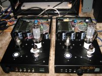
Got the amps finished last night, and listened on and off over 5 hours. Very promising! My own amps best them in most respects, but the new circuitry has a beguiling hear through quality- detail is often more apparent (my amps are no slouches in this respect), a product of the simplified signal path I suppose (just two active stages re three, and no interstage transformer), and, just occasionally, something sounds dramatically better! But much greyer- though much better with run in- no low bass (down to the low primary inductance of the the output transformers I suppose), a bit clanky, and much more confused in loud complex music. But I will certainly explore this topology for my own use soon!
In the meantime, I'll modify the driver stage to 20 mA plate current as Rod suggested, and listen again. And then install the shunt cascodes....
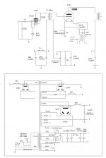
I've posted pictures of the modifed amps (they started life as Audion Silver Night Export PSE's), and also the circuit of my power amp (one PS per channel). As I said, I'll soon be fitting very high quality regs from Paul Hynes- shunt for the 300B B+, series for fixed bias
Paul
Got the amps finished last night, and listened on and off over 5 hours. Very promising! My own amps best them in most respects, but the new circuitry has a beguiling hear through quality- detail is often more apparent (my amps are no slouches in this respect), a product of the simplified signal path I suppose (just two active stages re three, and no interstage transformer), and, just occasionally, something sounds dramatically better! But much greyer- though much better with run in- no low bass (down to the low primary inductance of the the output transformers I suppose), a bit clanky, and much more confused in loud complex music. But I will certainly explore this topology for my own use soon!
In the meantime, I'll modify the driver stage to 20 mA plate current as Rod suggested, and listen again. And then install the shunt cascodes....
I've posted pictures of the modifed amps (they started life as Audion Silver Night Export PSE's), and also the circuit of my power amp (one PS per channel). As I said, I'll soon be fitting very high quality regs from Paul Hynes- shunt for the 300B B+, series for fixed bias
Paul
Attachments
Hi again
I converted the amps to run at a plate current of 20 mA and g2 at 150 V- just as Rod suggested. At first I thought- bizarrely!- that I preferred my initial set up- but after a few hours they now sound very good indeed. BTW 130R for the cathode load was bang on the money. (BTW it turned out the 6P14P I'd used for initial set up was very untypical- chosen at random it drew the lowest current of a sample of eleven I had to hand! I established the cathode load at 100R by trial and error before I discovered this- very irritating, but my own fault.)
Which makes me very tempted to play with alternative pentodes, as Rod and Yves suggested. Looking at Yves' circuit, with a zener to set the g2 voltage, I also wonder if a better use of the regulator I fitted would be to supply HT to the driver, rather than g2. The regulator's maximum dc input voltage is 400V, the maximum HT available would be ~375 V.
I should also have pointed out that the amps won't be driven by a separate preamp- they have input switching and attenuators on their inputs, designed to be driven directly by source components. At the moment the driver stage is, I estimate (I've yet to measure) giving a voltage gain of ~120, and, if anything, this a bit lower than ideal. Which of course makes Rod's shunt cascode even more attractive as final destination!
So would I be better off using the regulator for HT to the driver, and, with the need to maintain a minimum 40 dB gain in the driver stage, do I still have the option of a more linear driver?
Thanks
Paul
Probably best to regulate the driver HT, then pot down (and emitter-follower buffer) for the G2 voltage (pentode) or cascode voltage (shunt cascode).
Should work almost the same for both architectures.
Remember that LED bias gives more gain (than unbypassed Rk) but check the sound before painting yourself into a corner with it!
Should work almost the same for both architectures.
Remember that LED bias gives more gain (than unbypassed Rk) but check the sound before painting yourself into a corner with it!
Did you notice the other beneficial property of the shunt cascode?
There is effectively zero signal current, even instantaneous, in the HT capacitor. If you dislike cap colouration, you can build this driver, using stacked supplies and a thermally-coupled servo, and eliminate cap influence almost entirely.
There is effectively zero signal current, even instantaneous, in the HT capacitor. If you dislike cap colouration, you can build this driver, using stacked supplies and a thermally-coupled servo, and eliminate cap influence almost entirely.
- Status
- This old topic is closed. If you want to reopen this topic, contact a moderator using the "Report Post" button.