Anyone?
I have a pair of inter-stage transformers from Motorola consoles. They were used as phase splitters to drive four 6V6 output tubes in PPP.
I haven't been able to find any information on the transformers. And I'm not certain what was used to drive them as I only have the schematic for the power amp.
My question is this. If the transformer has a 1:1 ratio and is simply used to invert half the signal. Does the impedance have to be matched between the driver preamp tube and the output tube? I was thinking of using them between a 6SL7 or 6922 preamp tube and a pair of 6L6GC output tubes.
Kevin
Last edited:
My question is this. If the transformer has a 1:1 ratio and is simply used to invert half the signal. Does the impedance have to be matched between the driver preamp tube and the output tube?
No. From the theory of mutual inductance, a lightly loaded (Zsec >> (wM)^2) secondary has almost no effect on the primary circuit.
I was thinking of using them between a 6SL7 or 6922 preamp tube and a pair of 6L6GC output tubes.
It's not possible to use a 6SL7 that has rp= 44K with an IST. You need a triode with a considerably lower rp, and run it "hot" to get that rp down. Some thing like the large signal half of a 6DR7, 6BX7, or something like that. Your low frequencies start to fall off when Xl(pri)= rp.
You also need to find out how much DC those IST splitters were meant to carry as well.
this is a subject I don't understand, I do hope someone can clarify for me. ")
the transformer secondary will reflect to the primary the impedance presented to it.
this ignoring a zobel, will be the output tubes impedance, the plate-cathode?
effectively, its pretty high, near infinity, or whatever it may be, certainly 100s k or even meghoms.
that means the preceding valve will be loaded by if its 1:1, the same value neglecting losses. and presumably the other way around, the primary will match to the secondary what its loaded with, remember tx's don't work in isolation??
ie the 2dary will reflect its load to the primary, and vice versa?
so what does that mean for the load on the driver valve? near infinity?
what happens when we start say a 1:2 ratio?
I don't understand this area at all......can someone help explain in simple terms...
fwiw I think tx's are fascinating animals...
The inductance of the primary (it is a coil) is in parallel with the reflected impedance from the secondary. In a parallel combination the lower of the two dominates so once frequency gets low enough for the primary inductance to become dominant then it determines the response (in league with the driver tubes effective plate resistance).
A comparatively easy way to deal with the issues Miles raised and get the high gain a 6SL7 section offers is to buffer the common cathode wired triode with a DC coupled ZVN0545A source follower. Cap. couple the follower to the IST. Now, the trafo is being fed from a low impedance and no "standing" DC is present. You have to experiment with the value of the coupling cap., to get "flat" freq. resp., as the cap. interacts with the inductance of the trafo.
You have to experiment with the value of the coupling cap., to get "flat" freq. resp., as the cap. interacts with the inductance of the trafo.you might find some here Lundahl guidelines
and maybe study Lundahl spec sheets
you say it have been driving a PP output stage
means you have two secondaries (1+1)
do you have one or two primaries
1:1 with one primary should write 2:1+1
1:1 with two primaries should write 1+1:1+1
at least thats my understanding of it
and maybe study Lundahl spec sheets
you say it have been driving a PP output stage
means you have two secondaries (1+1)
do you have one or two primaries
1:1 with one primary should write 2:1+1
1:1 with two primaries should write 1+1:1+1
at least thats my understanding of it
The main issue you will have to deal with is interwinding capacitance which will sap the top end away. As Miles pointed out the only way to overcome this is to drive it with a super low impedance driver. This will also tend to help low end response.
Remember these things were only required to work out to about 15K so they will sound rolled off normally.
I have used a paralleled 5687 running at about 30mA in such a situation - it worked but only just. Something like an ECC99 will do the job in one bottle. Forget about using them as plate loads - go parafeed and use a blocking cap of about 4uf. There is a real possibility of a low frequency hump so test carefully.
Modern interstage transformers are very expensive because they attempt to overcome these intrinsic limitations by design. They can be as expensive as top end output transformers.
Shoog
Last edited:
In my professional opinion, I think it would be better to spec the transformer:
1st measure the DC resistance on both primary and secondary.
record your results.
with a signal generator, inject 100 mV of signal measure this at the primary and secondary with an oscilloscope, record results.
insert ac ammeter between the transformer primary and ground. inject 100mV of signal on the other end of the primary,
record your results.
once you have done that, we can discuss further designing your circuit properly.
DavesNotHere,
Here are those specs you asked for:
Transformer 1 Transformer 2
DC resistance
Primary gr/br 2.32k 2.34k
Secondary y/bk 3.04k 3.07k
Secondary r/bl 2.37k 2.41k
100mv @1k
Primary gr/br .100v .100v
Secondary y/bk .120v .120v
Secondary r/bl .120v .120v
Amperage Primary 1ma 1ma
I noticed that I had to reverse the leads on the Y/bk secondary to get a clean sign wave out.
I hope I've measured these correctly I'm a bit of an amateur with the scope. Thanks for any help you could provide.
Kevin
the dcr winding readings are a bit strange as they do not reflect the AC signal properties.
there should be two windings that are the same and one that will be different.
by using that logic, yel/blk would be the primary if I go with the dc resistance route, but the ac signal test makes it inconclusive.
do the test again, but use the yel/blk coil as the primary.
If I did my usual guesses, and just rely on the dc resistive data,
yel/blk is around 150k impedence
grn/brn is around 50k impedence
red/blue is around 50k impedence
but need to confirm voltage gain properties.
DavesNotHere,
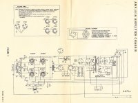
I ran the tests again. The DC resistance is correct. Also the primary is green/brown not the yellow/black. You can see this on the previous page schematic. Also, I removed the transformers from the chassis myself. The primaries had very short wires while the secondaries were about five inches long.
I used a high quality DVOM to measure the voltages again. With .100 volts AC at 1k on the primaries. I had .119 and .118 on the red/blue. And .133 and .138 on the yellow/black.
Kevin
ok, now looking at everything, you have a 40k input with a 47k and a 50k secondary screened with a 10k resistor in series with the transformer.
make sure you use the 15pf cap to reduce interference.
you might want to play with the 100k resistors to tweak the sound stage (47k-470k has been used historically here) the feedback decoupling cap (.01 cap in series with 100k resitor on the grid circuit) can be high as 1 uf however if you go big, I would suggest it to be bypass with a .01 uf cap A .47 uf cap would be a starting choice for me.
Last edited:
Thanks Again Dave,
But can I trouble you with another question? I see that the 39k resistor and the 2.33k primary are a resistor in parallel to come to about 40k. But I am not sure how you derive the 47k and the 50k? If I could understand that calculation it would be very helpful.
And then, if I have a 40k input to what exactly does that match up to on the original 6J5 preamp tube? And the 6V6 output tube. If I could understand these calculations I could modify the circuit to use the tubes I would like to use. Namely the 6l6 output, and whatever preamp tube I decide to use?
Thanks again, Kevin
Hello mr2racer,
You bring up an interesting topic, interstage transformers, and thank you. As I progress through DIYaudio I like to chunk of pieces to study in greater detail. It is like a puzzle I can’t leave it alone.
At one level transformers are just a pair of inductors that interact on the same core. They are voltage adjustors and impedance matchers blah blah. Dig deeper and the complexity is over your head quickly. Prof. Leach, RIP, used an approach to understanding electronics that makes it easier for me to get a grasp. Dr Leach would break down the item; resistor, capacitor or whatever into an equivalent circuit that when plugged into SPICE or my brain it would make scene.
Interstage transformers match the output impedance and voltage of the preceding stage to the next. The transformer equivalent circuit is not just inductance; there is also resistance and capacitance. Many times a matching network of resistors and capacitors (think zobel possibly) is added to tune the circuit.
I bought one of these EDCOR Electronics Corporation. S2S10Kt/10Kt to play with on the bench. The test tools are a signal generator and O’scope. I will start looking for square waves and then take a listen. It will be trial and error to start with.
DT
All just for fun!
interesting IT http://livinginthepast-audioweb.co.uk/pdf/vt1399-leaflet.pdf
Thanks Everyone,
When I saw a pair of these go for $150 dollars I figured they must be nice transformers. I was going to use them in a 6L6 amp I'm building. But I've decided trying to make them work correctly is beyond me at this point. So I'll stick to Hafler's original design.
Kevin
When I saw a pair of these go for $150 dollars I figured they must be nice transformers. I was going to use them in a 6L6 amp I'm building. But I've decided trying to make them work correctly is beyond me at this point. So I'll stick to Hafler's original design.
Kevin
- Status
- This old topic is closed. If you want to reopen this topic, contact a moderator using the "Report Post" button.
- Home
- Amplifiers
- Tubes / Valves
- interstage tansformer impedence