Nice work on the Sim, Jaz. That program looks a lot more logical. I looked into using a Voltmeter component on LTSpice, but it appears there isn't one! (not like TINA, anyway). When i try to run the sim, it's saying the potentiometers are invalid subcircuits. Oye! Will keep trying...
I did come across that one by Steve Conner - (i did a ton of searches on this before hand) and it looks useful, but a lot of power supply requirements and still using ICs, so I kept on looking.
I am confused a bit, were they not using fully-parametric EQ's in the studio back in the tube days? Cause I haven't found hardly anything along these lines in terms of schematics.
Hey Ian - glad to see you on here, I've been following your tube mixer project with the fella in Italy and also read thru your site, too. Impressive!!
Hey Ian - glad to see you on here, I've been following your tube mixer project with the fella in Italy and also read thru your site, too. Impressive!!
Thanks for the kind words. I have not heard from the guy in Italy for quite some time so I don't know if he ever finished his mixer.
Cheers
Ian
Just downloaded demo of TINA and am going to give it a go.
By the way, Jaz: Does the wiper of P3 (the .25M and .5M pots for bass freq) not need to go to ground?
Both sections of the LF frequency pot are connected to ground... Anyway, I think this particular design is not what we would call a parametric equalizer, it is more like a HF/LF shelving equalizer with adjustable corners and Q's.
As pointed out in the MEF thread, the tube-based studio parametric equalizers were just passive equalizer sections with tube buffers, while a gyrator is an ACTIVE device, i.e., it uses the gain of some type of active stage and capacitor to simulate the inductor.
Jaz
Thanks for summing that up, Jaz. Before I swallow the sadness of this down, I was wondering if you would mind posting a few other response curves - just to kind of show off the range of what this thing will actually do in its present form. (I built this in TINA but it says the Demo won't allow me to run such a large schematic!)
I once built a BPF with a pentode and at first i thought it was useless, then i tried it on a drum buss and it was incredibly cool, so it's not to say i won't build this thing anyway (just as a color on the palette), but would be great to get an idea of how versatile / non-versatile it is in advance.
I once built a BPF with a pentode and at first i thought it was useless, then i tried it on a drum buss and it was incredibly cool, so it's not to say i won't build this thing anyway (just as a color on the palette), but would be great to get an idea of how versatile / non-versatile it is in advance.
An externally hosted image should be here but it was not working when we last tested it.
HPF and LPF Corner Frequencies
Here are some more plots for your reference, I also connect the middle pin to ground on the HF frequency pots (missed it earlier, sorry about that). Anyway, you can see the responses are just peaks, you can't get dips (not as currently configured). If you are still interested in the idea of a tube buffered parametric EQ, here is one for you to try, you can have as many sections as you want, by adding more gyrators in parallel. As mentioned earlier, all this could be done much easier with ICs/FETs
")
An externally hosted image should be here but it was not working when we last tested it.
Jaz
Thanks Jaz. So i don't see much 'range' in those two, is this thing really that limited?
On that hybrid you posted, i only see one pot (boost/gain i guess?). Any ideas on adding Q and frequency?
I am fine with doing a hybrid, especially what i am hearing about doing it with tubes. Just looking for fully parametric (with the tube gain part if possible!)
On that hybrid you posted, i only see one pot (boost/gain i guess?). Any ideas on adding Q and frequency?
I am fine with doing a hybrid, especially what i am hearing about doing it with tubes. Just looking for fully parametric (with the tube gain part if possible!)
Yup, not much range at all and no cut only boost... wonder what it was designed for?
Sorry about the schematic, R3 (Q) and R5 (Freq) are suppose to be pots not resistors, you should be able to sim this in LTSpice or TINA. As currently configured, you got about 33dB of gain when in the "flat" position, which might be a tad too much already (anyway you can always add another pot either at the input or output to set the overall gain).
Jaz
Thanks for the post, Jaz.
So would r3's wiper go to r2? and would r5 be wired as a rheostat or..?
I wonder if another tube might be good for reducing that high gain a bit, maybe a 12au7 or something.
Did you find this schematic online or did you create it? Looks like a great option.
So would r3's wiper go to r2? and would r5 be wired as a rheostat or..?
I wonder if another tube might be good for reducing that high gain a bit, maybe a 12au7 or something.
Did you find this schematic online or did you create it? Looks like a great option.
The wipers are tied to pin 3 of the pots as shown in R.G.'s article. I think there are some online calculators that let you change the center frequency of the filters, then you just add more filter sections as needed, as they are all wired in parallel.
Jaz
Jaz
ah, i thought that looked slightly familiar...that's such a great article he did. and great job updating it for the tube stages, Jaz. As i recall, Keen has the formula on that article for calculating the target frequencies. i will check it out.
By the way, in my limited experience, i've never seen a diode hooked up to the cathode before, what's the story on that?
By the way, in my limited experience, i've never seen a diode hooked up to the cathode before, what's the story on that?
Seems you can get a range of 4.5:1 per simulated inductor. So, one inductor can go from 100hz to 450hz, the next one from 450hz to 2025hz, and a 3rd from 2025hz to 9112hz. And he does have the math in that article for selecting the right cap values.
Funny, if you look at my very first post, it mentions merging tubes with this schematic of RG's. And here i had come to think it was a daft idea....Thanks Jaz.
Funny, if you look at my very first post, it mentions merging tubes with this schematic of RG's. And here i had come to think it was a daft idea....Thanks Jaz.
I sim'd that on CircuitMaker 2000 and am getting similar results as you did.
I changed tube to a 12AU7 and put a pot on the output, so gain is in line now.
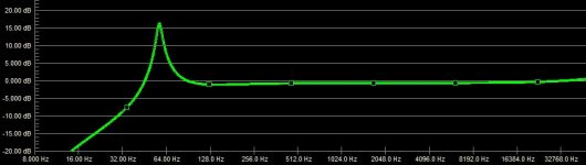
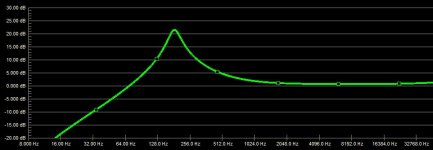
One thing I'm seeing is that when you increase the frequency, the Q changes (it's not as sharp, and is gutting a lot more sidebands) and the overall boost amount goes up too. But down at the low end of what this 'inductor' will do, it's nice and sharp.
Are you seeing this, too?
Attached are some screenshots: All i did was change the frequency pot from extreme low in one to extreme high in the other.
I changed tube to a 12AU7 and put a pot on the output, so gain is in line now.
One thing I'm seeing is that when you increase the frequency, the Q changes (it's not as sharp, and is gutting a lot more sidebands) and the overall boost amount goes up too. But down at the low end of what this 'inductor' will do, it's nice and sharp.
Are you seeing this, too?
Attached are some screenshots: All i did was change the frequency pot from extreme low in one to extreme high in the other.
Attachments
Hi there,
Yes, R.G.'s article the grand-daddy of the EQ articles online (there are many in textbooks though), anyway if you refer to Wikipedia, you can see that the Q is a function of f, so changing the center frequency will effect the Q.
As for LED or diode bias, it's nothing new, all you are doing is using the forward drop (typically 0.7 to 3V depending on the type used) to bias the stage, the advantage is that the stage can be fully bypassed without a capacitor, which is usually a good thing - also one less part to deal with...
Jaz
I guess I am used to software EQ's where you get this even Q across the whole range!
I'm not dismayed though, i call the discrepancies 'color'
Makes you get to know your gear better!
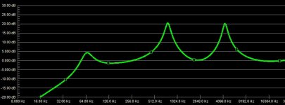
By the way, adding a couple more 'inductors' is working out really well.
Here's a screenshot....
I just wish i could get tighter Q in general. It's kinda gouging out sidebands. I've tried changing value of Q pot and a variety of other tweaks. Anyway, I'll keep plugging away...
I'm not dismayed though, i call the discrepancies 'color'
Makes you get to know your gear better!
By the way, adding a couple more 'inductors' is working out really well.
Here's a screenshot....
I just wish i could get tighter Q in general. It's kinda gouging out sidebands. I've tried changing value of Q pot and a variety of other tweaks. Anyway, I'll keep plugging away...
Attachments
Not sure if anyone can help, but I am trying to get a "flatter" response out of that low-frequency gyrator. I have everything over 256hz "kind of" flat (there are 6 bands now), but this low end has been a bugger. I've tried adjusting all kinds of values, but can't get it quite right. 
All settings are at half-way (freq and gain), Q at minimum.
Screenshot attached...
All settings are at half-way (freq and gain), Q at minimum.
Screenshot attached...
Attachments
I'm also experimenting with the parametric tone controls for my tube based bass guitar preamp.
This is what I initially came up with. Simulation results looks fine in Microcap,
but I will need to do some further research on (IRF510?) output stage, choice of opamps etc.
Low end control: 30-120Hz (variable Q)
Low/Mid control: 150-600Hz (variable Q)
High control: 1.5kHz fixed.
Any opinions?
BRs
Willem
Netherlands
Attachments
Hi PE2WDO,
Please keep me posted on how this goes. I am learning myself so i could hardly make worthy suggestions.
I'm curious - do you not need to buffer the output because it's going to go before the output stage in an amp? Or is that what "x20" is for (the last opamp before the output)?
In other news, I figured out the issue i was having. In my endless tweaking, i never put the Q pots back to 10k. Once i did, it 'sort of' worked out.
Attached is a screenshot. I added a LP filter on a switch, so that's what the 2nd line is on the image.
I guess the last issue i'd like to work out before ordering the parts is this: The first (lowest) band needs to be cranked to 80% boost to keep it 'flat-ish'. So, any suggestions from ye geniuses slumming it on my post are welcome as always!
Attachments
- Status
- This old topic is closed. If you want to reopen this topic, contact a moderator using the "Report Post" button.
- Home
- Amplifiers
- Tubes / Valves
- Fully Parametric Tube EQ (with gyrators)