Hi All
I have a Bell Sound 3DT that I have owned since 1981
It is all stock and still sounds great, but after 30 years of me owning it, and 55 years since it was new, I have decided to upgrade some caps and resistors. I got a hold of the Sam's Photofact and started investigating. I'm listining to Vinyl a lot so decided to do a nice job on the phono section as well and replace all the components in that section, and not just the caps.
Making a list of the components I needed and looking at the schematic to get an idea what to do first, and what components can be replaced together, I noticed that the Left and Right RIAA circuits are different ??
This model also has an eq for the tape head input ( THE original Bell 3D Didn't have a tape input, but this later 50's model did and was renamed the 3DT, Anyway). The tape eq circuit is the same for both channels, and this is implmented with the selector switch, which has a separate wafer that loops in a different feedback loop for each of the tape head and, phono inputs.
TAPE EQ
On the attached schematic the right channel (top) uses C45, R46 and C28 to EQ the tape head, this network is routed to "11" on the selector switch wafer "Sect 2 Rear M4" and the output of the stage, on pin "8" of the selector switch, is routed up through this network when the tape input is selected , this is exactly the same on the opposite channel... simple enough. (C7, R12 and C8 ) NOTE the schematic is drawn differently for each channel, but it is the same.
PHONO RIAA EQ
The phono RIAA network however, right channel (top) uses C26 and R44 in series and this is parralelled with R43 and C27, note that R44 is 240K. This network is connected to pin "12" of the selector switch wafer and the output of the stage is fed back through this network when the "Phono" input is selected on the selector switch. (And the tape EQ network left Open Circuit)
The left channel is ALMOST the same ... using R12 and C8 in series and then paralled with C6 and R13, but note the difference, and extra component.
R13 is 270K (but 240k in the right channel) and R12 the 20k resistor is shunted with a 3000mmf (3000 pf, the schematic is that old that they still use micro micro farad ) capacitor.
So what's up. I have looked into the bottom of the unit and sure enough this is how it is..
So if I replace these components, I'm thinking that I should make both channels identicle, using 1% metal film resistors and 5% poly caps, but what channel to copy ?
Ideas ??
Simon
Attachments
Last edited by a moderator:
So,
Nobody is curious as to why one of the worlds first stereo amplifiers had an asymetrical RIAA circuit ?
And no suggestions on which channel to use as in the rebuild, or if I should change any of the values ?
The phono section currently actualy sounds decent, (Compared to my Modified PAS-3, and my 6dj8 phono stage which I installed into my SCA-35)
Hey Palustris
I'll get back under the hood of the Bell 3DT and double check, it is possible that I was looking at the capacitor shunt on the tape circuit, but I'm usually pretty good at identifying things. But granted the point to point wiring isn't always symetrical either so identifying things isn't as easy as it may appear.
I'll do a more through ID of the components later in the week, but right now I'm using the Bell as my main system while my custom Pre Amp is having all the resistors replaced with 1% PRP's from Parts Connexion
Simon
Confirmed,
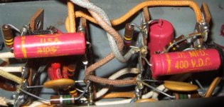
A couple of the RIAA network resistors are different in each channel, but should be the same I would think.
A 240K, (Red, Yellow, Yellow) in one channel
And a 270K (Red, Violet, Yellow) in the other. As seen in the attached photo.
Also the additional capacitor that shunts the 20K resistor in only one channel is there, and visable in the bottom right hand corner of the attached photo.
So, not an error in the Sams PhotoFact. The physical components are they as per the schematic.
SO, as I replace the components in this Vintage Classic, what channel do I use as a model for the new resistors, and why were the 2 channels not identicle to start with ?
Attachments
The right (top) channel is wrong, as it is missing the HF rolloff which C7 gives the left channel. Unless for some peculiar reason this rolloff is inserted in a later stage. Does the right channel seem rather 'bright' on phono?
This could be a 'Friday afternoon' design - assuming such things happen in the USA?
This could be a 'Friday afternoon' design - assuming such things happen in the USA?
Hi DF96
Thanks for the comment, I will add a C7b to opposite channel when I replace the components. But why the different resistor values ?
The sound is fine, The Phono sounds better than the CD player. (As it should )
I was listening for a audible difference, but could not notice anything. Most of the components are 10% and after 55 years, the two channels are most likely not that close to each other anymore anyway.
This was one of the first commercial stereo products, a real gem of a collectors item now, and it is surprising that the engineers would have missed something like this. For some reason it must have been an intentional circuit. The Bell 3D was based on an earlier Mono design. Maybe I should have a look for that schematic and see what the RIAA looks like.
The unit I have is actually a 3DT , a later unit from the late 50's that had a Tape input, and a EQ network for that input. Perhaps I should also look at the schematic for the original 3D and see what it's RIAA looks like.
But why the different resistor values ?
Perhaps they were measured and selected to a matched value?
Sheldon
Bell 3CT, Phono RIAA oddity
Hi folks, late reply, I think the last post was in 2011--anyway, maybe I can help answer your questions as to why the RIAA EQ was different in the left and right channels of the phono stage of the Bell 3D and 3DT. This unit was designed and built BEFORE there were the stereo records we know, and was to be used with the Cook Binaural recordings that required two mono cartridges mounted to the tonearm, with the cartridges separated from each other in the horizontal plane by a defined distance, to play these special discs, which were recorded with one channel cut on the outer half of the disc, and the other channel cut on the inner half of the disc. The EQ was different for the channels because there was apparently a problem with high frequency distortion in cutting and playing the inner grooves on the inner half of the disc due to the much lower groove velocity of these inner grooves, so during cutting, a different pre-emphasis curve was developed for the inner grooves, to help lower the playback distortion. Consequently, the de-emphasis in that channel of the 3D/3DT phono stage also had to be different in order to compensate for the different pre-emphasis curve on that part of the binaural disc.
Hi folks, late reply, I think the last post was in 2011--anyway, maybe I can help answer your questions as to why the RIAA EQ was different in the left and right channels of the phono stage of the Bell 3D and 3DT. This unit was designed and built BEFORE there were the stereo records we know, and was to be used with the Cook Binaural recordings that required two mono cartridges mounted to the tonearm, with the cartridges separated from each other in the horizontal plane by a defined distance, to play these special discs, which were recorded with one channel cut on the outer half of the disc, and the other channel cut on the inner half of the disc. The EQ was different for the channels because there was apparently a problem with high frequency distortion in cutting and playing the inner grooves on the inner half of the disc due to the much lower groove velocity of these inner grooves, so during cutting, a different pre-emphasis curve was developed for the inner grooves, to help lower the playback distortion. Consequently, the de-emphasis in that channel of the 3D/3DT phono stage also had to be different in order to compensate for the different pre-emphasis curve on that part of the binaural disc.
the cartridge picks up horizontal movements as one channel and vertical movements as the other. This guys may have known that the EQ is required to be different for max sound quality. if this is the case, a speaker connected across Left (+) and right (+) will yield L-R. if the balance is required the sound will be louder with the phono inputs reversed.
Here are some excerpts I found in the Wikipedia that relate to this subject-- (the excerpts are all enclosed in quotes ("):
"Emory Cook
In 1952, Emory Cook (1913–2002), who already had become famous by designing new feedback disk-cutter heads to improve sound from tape to vinyl, took the two-channel high-fidelity system described above [INSERT: which, in my opinion, had serious shortcomings--for several reasons; read the complete Wikipedia article here at: https://en.wikipedia.org/wiki/Stereophonic_sound#Early_work --R. H. 7/17/2015] and developed a somewhat misnamed "binaural" record out of it, which consisted of the same two separate channels cut into two separate groups of grooves running next to each other as described above, i.e. one running from the edge of the disc to halfway through and the other starting at the halfway point and ending up towards the label, but he used two lateral grooves with a 500 Hz crossover in the inner track to try and compensate for the lower fidelity and high frequency distortion on the inner track.
Each groove needed its own monophonic needle and cartridge on its own branch of tonearm, and each needle was connected to a separate amplifier and speaker. This setup was intended to give a demonstration at a New York audio fair of Cook's cutter heads rather than to sell the record; but soon afterward, the demand for such recordings and the equipment to play it grew, and Cook Records began to produce such records commercially. Cook recorded a vast array of sounds, ranging from railroad sounds to thunderstorms.[note 1] By 1953, Cook had a catalog of about 25 stereo records for sale to audiophiles.[27]
Magnetic tape recording
Stereo magnetic tape recording was demonstrated on standard 1/4-inch tape for the first time in 1952, using two sets of recording and playback heads, upside-down and offset from one another.[28] A year later, Remington Records began recording a number of its sessions in stereo, including performances by Thor Johnson and the Cincinnati Symphony Orchestra.
Later that same year, more experimental stereo recordings were conducted with Leopold Stokowski and a group of New York studio musicians at RCA Victor Studios in New York City. In February 1954, the label also recorded a performance of Berlioz' masterpiece The Damnation of Faust by the Boston Symphony Orchestra under the direction of Charles Münch, the success of which led to the practice of regularly recording sessions in stereo.
Shortly afterwards, the last two public concerts directed by famed conductor Arturo Toscanini were recorded on stereophonic magnetic tape, however they were not released as such until 1987 and 2007, respectively. In the UK, Decca Records began recording sessions in stereo in mid-1954, and by that time even smaller labels in the U.S. such as Concertapes, Bel Canto and Westminster along with major labels such as RCA Victor began releasing stereophonic recordings on two-track prerecorded reel-to-reel magnetic tape, priced at twice or three times the cost of monaural recordings, which retailed for around $2.95 to $3.95 apiece for a standard monaural LP. Even two-track monaural tape which had to be flipped over halfway through and carried exactly the same information as the monaural LP - but without the crackles and pops - were being sold for $6.95.[29]
One has to understand that, in the United States, the average working man in 1954 might be taking home $50–$60 a week if he was lucky and paying $75–$100 a month in rent for his two-room apartment. Therefore the price of a great deal of two-track stereo tape recordings of the period being upwards of $12.95-$18.95 apiece for a full-length album when the corresponding mono LP was only $3.95, would be prohibitive. In addition, the cost of the stereophonic recorder upon which to play them may have been equal to or greater than the cost of a new car.
However, audiophiles, with little or no regard for the cost, bought them and the players anyway, and stereophonic sound came to at least a select few living rooms of the mid-1950s.[30] Stereo recording became widespread in the music business by the 3rd quarter of 1957.
Stereo on disc
Label and sleeve from Audio Fidelity Records' second stereo demonstration record, ca. 1958.
In November 1957, the small Audio Fidelity Records label released the first mass-produced stereophonic disc. Sidney Frey, founder and president, had Westrex engineers, owners of one of the two rival stereo disk-cutting systems, cut a disk for release before any of the major record labels could do so.[31][32] Side 1 featured the Dukes of Dixieland, and Side 2 featured railroad and other sound effects designed to engage and envelop the listener. This demonstration disc was introduced to the public on December 13, 1957 at the Times Auditorium in New York City.[33] Only 500 copies of this initial demonstration record were pressed and three days later, Frey advertised in Billboard Magazine that he would send a free copy to anyone in the industry who wrote to him on company letterhead.[34][35] The move generated such a great deal of publicity[36] that early stereo phonograph dealers were forced to demonstrate on Audio Fidelity Records.
Also in December 1957, Bel Canto Records, another small label, produced its own stereophonic demonstration disc on multicolored vinyl so that stereo dealers would have more than one choice for demonstration. With the supplied special turntables featuring a clear platter lighted from underneath to show off the color as well as the sound, the stunt worked even better for Bel Canto, whose roster of jazz, easy listening and lounge music, pressed onto their trademark Caribbean-blue vinyl sold well throughout 1958 and early into 1959."
"It seems several other companies were joining the binaural bandwagon including a Livingston twin-channel binaural preamplifier plus a power supply and 10-watt/ch amplifier in a matching cabinet all for $149.50. Bell Sound Systems had a Model 3-D 10-watt/ch integrated amplifier with power supply. Bozalk was advertising the B-204 binaural speaker system."--an excerpt from this Roger Russell article here: Emory Cook binaural
So it seems that the model "3D" was Bell's marketing statement about what eventually became "STEREO" rather than binaural, and the "3D" must have meant "3-dimensional". I found out that the 3DT was next year's model, in which Bell added a "Tape Head" input position on the selector switch. The 3D only had one low level input, Phono. This Tape Head input on the 3DT model allowed stereo tapes to be played directly from the playback head on a tape deck.
--Robert
Late reply, but here goes. I would have both channels wired identical to the RIAA curve. This was adopted after multiple EQ settings were used to cut records and you have to select the proper EQ curve for playback in the 1950's. The RIAA became the standard in 1954. So as this amp was being designed in the 50's, the playback curve for records was not standardized. From 1954 on, most all records were cut using the RIAA curve.
I believe the mono version of this amp, the 2200C, had multiple selector choices for record playback INCLUDING the RIAA curve.
So, it was just a time lag that probably resulted in the design difference of the two channels. You WANT to have both channels the same, whichever route you take.
I believe the mono version of this amp, the 2200C, had multiple selector choices for record playback INCLUDING the RIAA curve.
So, it was just a time lag that probably resulted in the design difference of the two channels. You WANT to have both channels the same, whichever route you take.
Late reply....
Ah, let sleeping dogs lay.
Too late.
The difference 240K or 270K is a dB below 50Hz. Insignificant. Not even easy to test for on 1950 gear. While today it is routine to do parity-check, that may not have been obvious to the draftsman of the first stereo working from the prototype's handwritten notes. I have seen handwriting where "4" and "7" could be confused. They are both 5% parts. Probably a goof-up that was never noticed.
As said, the lack of the 3,000pFd is "wrong" for most electric recordings. Theories about how the forked-arm recordings were EQ-ed is beyond my ken. With any "stereo" recording and pickup you are likely to have, you do want about 3000pFd there.
> playback curve for records was not standardized.
Yes and no. Commercial consumer recordings had many published curves. Broadcast transcriptions were already an NAB standard. The RIAA Standard is essentially the NAB standard with more detail.
The hilarious thing is: w/3000p, this preamp IS the NAB/RIAA standard!! +/-1dB from 50cps to 5kc, can't complain about that. The rise above 5kc may be tamed by roll-offs in later stages or stray capacitance; IAC another dB above 10KHz is nothing compared to the tweeters of the day.
In schematic, V17 is a hack for the sim's failure to grid-leak bias as real tubes do, to get the right op-point.
Attachments
Last edited:
Hi folks, late reply, I think the last post was in 2011--anyway, maybe I can help answer your questions as to why the RIAA EQ was different in the left and right channels of the phono stage of the Bell 3D and 3DT. This unit was designed and built BEFORE there were the stereo records we know, and was to be used with the Cook Binaural recordings that required two mono cartridges mounted to the tonearm, with the cartridges separated from each other in the horizontal plane by a defined distance, to play these special discs, which were recorded with one channel cut on the outer half of the disc, and the other channel cut on the inner half of the disc. The EQ was different for the channels because there was apparently a problem with high frequency distortion in cutting and playing the inner grooves on the inner half of the disc due to the much lower groove velocity of these inner grooves, so during cutting, a different pre-emphasis curve was developed for the inner grooves, to help lower the playback distortion. Consequently, the de-emphasis in that channel of the 3D/3DT phono stage also had to be different in order to compensate for the different pre-emphasis curve on that part of the binaural disc.
I found this. Note the two heads on the tonearm:
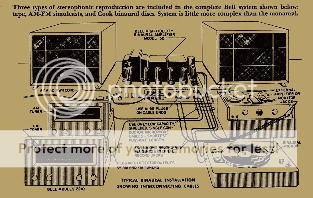
...to be used with the Cook Binaural recordings that required two mono cartridges.... The EQ was different for the channels because there was apparently a problem with high frequency distortion in cutting and playing the inner grooves on the inner half of the disc due to the much lower groove velocity of these inner grooves, so during cutting, a different pre-emphasis curve was developed for the inner grooves.....
Confirmation from historical publication.
Attachments
- Status
- This old topic is closed. If you want to reopen this topic, contact a moderator using the "Report Post" button.
- Home
- Amplifiers
- Tubes / Valves
- Bell Sound 3DT, Phono RIAA Odditty