Interesting arrangement Steve. How would you calculate the feedback ratio? I do see where it might require a scope to insure that you aren't getting oscillation from the complex impedances involved.
Well the short answer is that you can't. It's a bit of a kludge really as the proper method would be to have a properly specified tertiary feedback winding, like the Mc Intosh amps or the Quad II. You can get different levels of feedback by experimenting with unused secondary windings. It might work well on one amp but not on others.
I got the idea orifinally from Morgan Jones "scrapbox challenge" SET
The idea to just take the feedback via the bypass cap leaving the cathode resistor grounded came from a guy on this very forum.
Hey Steve,
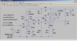
There is yet three alternative ways to arrange a Schade and use other drivers than a pentode. And NO it is not the doubtful and high distortion RH solution.
The first: By adding a series resistor between the drivers anode and the junction between the feedback resistor and the output tubes input cap you get an anodefollower. See th eaxmple below. On the downside is the eventual Miller-effect in this giving something like 100k -3db.
The second is the original Schade with transformer-coupling.
The third is using a depletion MOSFET like MJK does.
But personally I think a pentode like you use is the best. Maybe I should go for E280F or D3a. But then we loose the low budget approach.
The schematic is just as an example of the first.
Attachments
Last edited:
But personally I think a pentode like you use is the best. Maybe I should go for E280F or D3a. But then we loose the low budget approach.
The schematic is just as an example of the first.
Cheers Lars,
Yes.... these amps were built to a budget. 6AU6 is very cheap and I was given the PL509s by a fellow valve enthusiast.
I'd love to do a direct heated pentode SEP but could never afford the iron
")
Steve
lars;
Your last schematic is almost exactly what I am doing on power amp section of my KT88 mini-console project except that I am not using an active load on the driver. I don't have any proper measuring equipment but so far it sounds pretty decent given the ancillary equipment that I am using with it for initial testing.
Your last schematic is almost exactly what I am doing on power amp section of my KT88 mini-console project except that I am not using an active load on the driver. I don't have any proper measuring equipment but so far it sounds pretty decent given the ancillary equipment that I am using with it for initial testing.
That is exactly the kind of feedback I use on my EL34/ KT77 SEP. The feedback ratio depends on the impedance ratio of the OPT, the lower the impedance ratio the higher the feedback, to the point of making the amplifier a buffer with gain under unity, if the impedance ratio is low enough. So basically you may calculate it from the voltage relations, but the amount of it is pretty limited!
My OPT is 4500K / 6 ohm, so I dont have much of it,,,,
My OPT is 4500K / 6 ohm, so I dont have much of it,,,,
Last edited:
- Status
- This old topic is closed. If you want to reopen this topic, contact a moderator using the "Report Post" button.