Disclaimer: I've made some assumptions here, since I don't know everything about this... I've tried to think it through though 
The main problem with the Futterman is that the NFB is imbalanced. The top tube is a cathode follower, yet the bottom is a standard plate follower with no more NFB than the triode used (and with a load 1/4 or less of the plate resistance, there isn't much internal NFB left!). As a result, there will be much 2nd harmonic in the output. This is usually fixed by using a cathodyne phase splitter grounded to the output, and inverting the drive phase to the output tubes. That helps a little but is only masking the deficiencies of the topology.
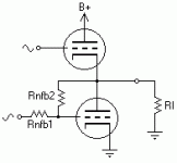
I propose using shunt NFB applied to the bottom tube, as shown in the attached drawing (note: drawn for theory only). Say you drive it with 20V, and the tube produces a voltage gain of 5 in the circuit conditions. Then the plate signal output is 100V. Yet the same conditions with a CF produces an output of 16.6V, or 15.5dB of NFB. To balance the circuit requires the same amount of NFB applied to the bottom. But how?
Driving the grid through a high resistance, and applying some of the plate signal back to the grid, we form a voltage divider from input to output, with the grid inbetween. To solve this, we assume the input and output - 20 and -16.6V (it's inverse polarity remember) respectively, and then since the tube still has a gain of 5, grid voltage must be 3.3V. So there are 16.7V across the input resistance, and 20V between grid and output. The scale of the resistance should depend on HF constants (capacitance, etc.) and the possible driver Zo (for instance if driving with a pentode, the Rp will be a significant portion of the 'input resistance').
The advantage is that for two extra resistors (maybe just one if driven by a pentode) you balance the output; however since a CF's NFB is applied in series, whereas this is shunted, the characteristics vis-a-vis changing Rl will unbalance it at anything other than a certain impedance. I think!
Erm.. hope that makes sense Comments?
Tim
The main problem with the Futterman is that the NFB is imbalanced. The top tube is a cathode follower, yet the bottom is a standard plate follower with no more NFB than the triode used (and with a load 1/4 or less of the plate resistance, there isn't much internal NFB left!). As a result, there will be much 2nd harmonic in the output. This is usually fixed by using a cathodyne phase splitter grounded to the output, and inverting the drive phase to the output tubes. That helps a little but is only masking the deficiencies of the topology.
I propose using shunt NFB applied to the bottom tube, as shown in the attached drawing (note: drawn for theory only). Say you drive it with 20V, and the tube produces a voltage gain of 5 in the circuit conditions. Then the plate signal output is 100V. Yet the same conditions with a CF produces an output of 16.6V, or 15.5dB of NFB. To balance the circuit requires the same amount of NFB applied to the bottom. But how?
Driving the grid through a high resistance, and applying some of the plate signal back to the grid, we form a voltage divider from input to output, with the grid inbetween. To solve this, we assume the input and output - 20 and -16.6V (it's inverse polarity remember) respectively, and then since the tube still has a gain of 5, grid voltage must be 3.3V. So there are 16.7V across the input resistance, and 20V between grid and output. The scale of the resistance should depend on HF constants (capacitance, etc.) and the possible driver Zo (for instance if driving with a pentode, the Rp will be a significant portion of the 'input resistance').
The advantage is that for two extra resistors (maybe just one if driven by a pentode) you balance the output; however since a CF's NFB is applied in series, whereas this is shunted, the characteristics vis-a-vis changing Rl will unbalance it at anything other than a certain impedance. I think!
Erm.. hope that makes sense
Tim
Hi,
It does...
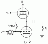
Only you seem to forget that your local NFB loop will also put a DC voltage on the output.
Cheers.
Erm.. hope that makes sense Comments?
It does...
Only you seem to forget that your local NFB loop will also put a DC voltage on the output.
Cheers.
- Status
- This old topic is closed. If you want to reopen this topic, contact a moderator using the "Report Post" button.
- Home
- Amplifiers
- Tubes / Valves
- Improving the Futterman

