Hi all. I'm at my wits end here, I honestly am just completely confused and without a clue on how to proceed. I've been building tube electronics for a few years now, and all of my previous builds have been based off full schematics which include power supplies. Now, I've decided to tackle a new project with a schematic that doesn't include a power supply, but rather just a "+1100v" for the B+/ HV.
I'm not an expert at power supplies, but I do have a basic understanding of DC smoothing and rectification. I've opted to go with Mercury Vapor 866a rectifiers, because I like the glow and got them cheap, and they can handle my requirements.
I will note right now that this is not an audio amp I'm building, it's actually an audio modulated 180m transmitter. So, when you look at the schematic, understand it's a transmitter and not an amp. (Though I suppose it includes a pre-amp circuit nonetheless)
Here's the schematic I'm working off of:
AM Window: Tech: General: Series Modulated 807 (the pdf is high-res)
I'm using 6GW6/ 6DQ6B as opposed to the expensive 6LF6's.
So, I will be using a power transformer with 1160 VCT @ 175ma max, rectified by two 866a's in full wave.
I just don't know how to filter the damn thing. I am on a ridiculously tight budget as of now, so cheap is good. I've looked at using an LC with and 18H choke and a 4uF cap, but I'm not sure how to calculate my idle current draw if no audio is fed. It would need to be above about 64ma for an 18H choke, and above 105 for a 10.5H choke, which I also have access to.
If anyone here could provide help as to how much current this thing will actually draw, I would be very grateful.
I'm also considering doubling up on the 807's, and adding another audio amp circuit. (remember I am using 6GW6/ 6DQ6B instead of 6LF6) So, in total, if I do add a second tube, I would be at two 807's in PP, total of 4 6GW6, and 2 12AU7's, plus the 6AG7. But this would be after I finish it as laid out in the schematic.
I really am so lost. Maybe a stack of series electrolytics would work better for filtering, but I have no clue right now.
-Steve
Hi all. I'm at my wits end here, I honestly am just completely confused and without a clue on how to proceed. I've been building tube electronics for a few years now, and all of my previous builds have been based off full schematics which include power supplies. Now, I've decided to tackle a new project with a schematic that doesn't include a power supply, but rather just a "+1100v" for the B+/ HV.
To say that it's incomplete is a definite understatement.
1) He's got a modulated CCS in the tail of the 807, and no DC voltages
 The voltage across a CCS is undefined by nature, and without the voltages, how can you adjust its bias to get the necessary voltage at the 807 cathode?
 2) No guard bias. If the master oscillator fails to start, no bias for the 807
 Insta-poof! Needs a bypassed cathode resistor (RF and AF) to provide at least some hold-off bias.
So, I will be using a power transformer with 1160 VCT @ 175ma max, rectified by two 866a's in full wave.
If anyone here could provide help as to how much current this thing will actually draw, I would be very grateful.
The key here is that #47 pilot lamp in the Vpp main. It's rated for 150mA @ 6.3V. You won't be pulling more than 150mA, but I sure wouldn't rely on that to save the 807 if something goes wrong. With some 1100V, it could easily flash over or strike an arc if the filament burns out. Your "fuse" won't be a fuse if that happens.
I would download this: Rectifier Applications Handbook. That should tell you what you need to know to design a functional choke input filter (and if you insist on using 866s, then you'll require a choke input filter since Hg-vapor diodes don't stand up to Isurge very well).
Also needs a HPF in the audio signal chain to cut the highs above 3.0KHz, since SW AM has a 6KHz BW limit.
Last edited:
Steve, it sounds like you really are pushing your death-wish limits here! It is another world of experience needed when you start getting over 1kV.
Choke insulation to core may be exceeded unless you have a modern choke which has passed 2kVrms flash test. Alternatively, you could poor-man insulate the whole choke.
You will need separate heater transformers, which will also need at least 2kV flash compliance. And a time delay for HT application.
Choke regulation loading has to use high voltage rated resistors, although is easiest done with series capacitor balancing resistors. 250-275VAC poly caps for mains suppression often have up to 760VDC rating.
Well worth adding a primary side NTC resistor turn-on limiter with delayed relay bypass to limit peak diode current.
This takes me back to building pirate rigs in the 60's and early 70's.
We'll make a few assumptions.
For 100% modulation then the half way volts (cathode of 807) will be 550V.
Max RF output for an 807 is 40W, with 25W anode dissipation. So total is 65W, plus a tiny bit for the screen grid, lets just stick to 65W. That works out at 120mA (well 118 actually).
As the modulator is class A then the average current draw should stay about the same.
Have to say running a 1100 Volt supply does seem rather scary, rather you than me!
please be careful.
Regards
Henry
You might want to put the power supply inductor on the - side of the power supply rather than on the + side. Less voltage stress for the inductor.
Overall, it's an interesting design. Series modulation. Gates/Harris did this many years ago on their MW line of AM transmitters. The only difference is that they used pulse width modulation and filtered out the 70kHz pulses between the modulator anode and the RF PA cathode.
Please be careful with the voltage. It's lethal.
Hey guys. I must say, you all rock. Already received more useful info than at some *other* forums and sites.
I'm aware of the danger with 1100V, I've done 2kv+ work before so I'll do what I can.
I played around with PSUD2 and used their 575 model, since it's MV it will have nearly the same voltage drop. With an 18H choke I came up with something like 1050V? I need to go through and calculate what the total resistance of this circuit will be.
well, the caps used are usually ones in RF transmitters, there in the neighborhood of $70-$120. Surplus shops and ham radio swap meets are your friends when it comes to sourcing these parts.
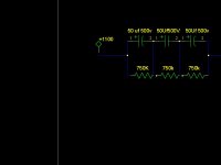
you can stack electrolytics end on end with voltage stabilizing resistors. but if you need large values, its better to use the rf oil caps.
the drawing is an example of a 16 Uf 1500V cap made from 3 50 Uf 500V caps.
you can stack electrolytics end on end with voltage stabilizing resistors. but if you need large values, its better to use the rf oil caps.
the drawing is an example of a 16 Uf 1500V cap made from 3 50 Uf 500V caps.
Attachments
well, the caps used are usually ones in RF transmitters, there in the neighborhood of $70-$120. Surplus shops and ham radio swap meets are your friends when it comes to sourcing these parts.
you can stack electrolytics end on end with voltage stabilizing resistors. but if you need large values, its better to use the rf oil caps.
the drawing is an example of a 16 Uf 1500V cap made from 3 50 Uf 500V caps.
I'm going to use that in addition to the choke I have. (18H, 120ohms). PSUD2 shows that will smooth nicely and give about 1040V, which is close enough for me to be happy.
Someone mentioned hooking the choke up to the negative side- I am wondering why that might be a better choice?
SK
So that the insulation doesn't have to tolerate well over a KV between windings and core.
Ok, that makes a lot of sense. Now the only other question that I have is if I use the negative side, do I still put the choke BETWEEN the transformer and capacitors? Or would the choke now go on the circuit side of the caps?
Hope that was clear, lol.
Steve
- Status
- This old topic is closed. If you want to reopen this topic, contact a moderator using the "Report Post" button.
- Home
- Amplifiers
- Tubes / Valves
- Power Supply Help- 807's, High Voltage