Hello,
For those that don't want to read much in the last paragraph is described the issue.
I am new in this forum and also in valve amplifiers construction. I think the better way to start is to introduce myself: I am Telecommunication Engineer and also a music player and lover. I am in a group of music where I need to use a transducer in order to electrify my violin: it is a Fishman pickup (V-200 Classic Series Professional Violin Pickup - Fishman Transducers, Inc.). The pickup is a good one and in the last years I've been frustrated because I didn't like the sound I was getting. I usually connect directly the pickup into an inexpensive mixer console. I recently discovered that this issue can be overcome by using a preamplifier: the transducer has a very high output impedance (capacitive), which steals bass when not matched. I love the tube sound and I want that on my preamplifier, but all preamplifiers sold for acoustic instruments that I found was solid state based.
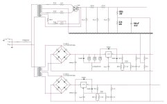
So, I decided to make my first tube preamplifier. The requirements are the following: high input impedance, low output impedance, tone control, clean sound and minimum distortion. To fulfill this criteria I considered a design composed of four stages: a buffer input stage to match the piezoelectric impedance, a mu follower stage to get some gain before the next stage, a Baxandall tone control circuit (bass/treble 20 dB boost/cut) and the last stage is a mu follower to get low ouput impedance with minimum distortion and to rise signal to line level. In my calculations, E88CC is a good preamplifier tube to make the mu followers because it has enough voltage gain for my purpose and high transconductance, which is interesting to reduce noise. In the power supply design I decided to include a tube rectifier, specifically an EZ81 for HT. Upper valve cathode is about 220 Volts whilst lower valve cathode is about 2.5 Volts. So, I decided to put upper valves in one bottle, lower valves in another. The maximum voltage between cathode and heater for E88CC is about 50 Volts, so I need to use two separate LT supplies for each bottle, one elevated near 220 Volts. To do this, I followed the design found in Morgan Jones book (you can find a schematic below). Input impedance of a tube based stage cannot be greater than about 1 MegOhm which is not enough (due to maximum grid leak resistor value). So, to overcome this I resorted to solid state, specifically a buffer stage based on an audio operational amplifier. This requires a symmetrical supply, so my aim is to use the non elevated heater supply to feed the operational amplifier as well.
I must admit that I hadn't worked previously with valves and all I know is from reading books/articles like the Morgan Jones ones. I followed his book "Valve amplifiers" to help me in my design. I also used PSpice and PSU2 to simulate the circuits. Well, all my calculations and simulations seems to go very well and I decided to build it.
I found a problem in the power supply that I want to discuss with you that is going to make me mad (you can find a schematic below to follow the description). The elevated supply does not rise to 220 Volts, it is elevated to about 20 Volts instead and doesn't give 6.3 Volts between its terminals as it was supposed to do. On the other hand, the non elevated supply is slightly non symmetrical (+3.5/-2.8V instead of +3.15V/-3.15V). I checked all during some days and everything seems to be ok. Now observe the following: suppose that we disconnect the center tap formed by 47 Ohm resistors in the non elevated LT supply from ground (leaving the resistor leads not connected). In this situation, the elevated supply works perfect as it was supposed to do, but the non elevated supply is now elevated like about 300 Volts. This time suppose that we disconnect the elevated supply from the potential divider instead of the non elevated supply. Now, the non elevated supply is perfectly symmetrical (+3.15V/-3.15V). Any ideas of what can be wrong? Thanks for your time in reading this.
For those that don't want to read much in the last paragraph is described the issue.
I am new in this forum and also in valve amplifiers construction. I think the better way to start is to introduce myself: I am Telecommunication Engineer and also a music player and lover. I am in a group of music where I need to use a transducer in order to electrify my violin: it is a Fishman pickup (V-200 Classic Series Professional Violin Pickup - Fishman Transducers, Inc.). The pickup is a good one and in the last years I've been frustrated because I didn't like the sound I was getting. I usually connect directly the pickup into an inexpensive mixer console. I recently discovered that this issue can be overcome by using a preamplifier: the transducer has a very high output impedance (capacitive), which steals bass when not matched. I love the tube sound and I want that on my preamplifier, but all preamplifiers sold for acoustic instruments that I found was solid state based.
So, I decided to make my first tube preamplifier. The requirements are the following: high input impedance, low output impedance, tone control, clean sound and minimum distortion. To fulfill this criteria I considered a design composed of four stages: a buffer input stage to match the piezoelectric impedance, a mu follower stage to get some gain before the next stage, a Baxandall tone control circuit (bass/treble 20 dB boost/cut) and the last stage is a mu follower to get low ouput impedance with minimum distortion and to rise signal to line level. In my calculations, E88CC is a good preamplifier tube to make the mu followers because it has enough voltage gain for my purpose and high transconductance, which is interesting to reduce noise. In the power supply design I decided to include a tube rectifier, specifically an EZ81 for HT. Upper valve cathode is about 220 Volts whilst lower valve cathode is about 2.5 Volts. So, I decided to put upper valves in one bottle, lower valves in another. The maximum voltage between cathode and heater for E88CC is about 50 Volts, so I need to use two separate LT supplies for each bottle, one elevated near 220 Volts. To do this, I followed the design found in Morgan Jones book (you can find a schematic below). Input impedance of a tube based stage cannot be greater than about 1 MegOhm which is not enough (due to maximum grid leak resistor value). So, to overcome this I resorted to solid state, specifically a buffer stage based on an audio operational amplifier. This requires a symmetrical supply, so my aim is to use the non elevated heater supply to feed the operational amplifier as well.
I must admit that I hadn't worked previously with valves and all I know is from reading books/articles like the Morgan Jones ones. I followed his book "Valve amplifiers" to help me in my design. I also used PSpice and PSU2 to simulate the circuits. Well, all my calculations and simulations seems to go very well and I decided to build it.
I found a problem in the power supply that I want to discuss with you that is going to make me mad (you can find a schematic below to follow the description). The elevated supply does not rise to 220 Volts, it is elevated to about 20 Volts instead and doesn't give 6.3 Volts between its terminals as it was supposed to do. On the other hand, the non elevated supply is slightly non symmetrical (+3.5/-2.8V instead of +3.15V/-3.15V). I checked all during some days and everything seems to be ok. Now observe the following: suppose that we disconnect the center tap formed by 47 Ohm resistors in the non elevated LT supply from ground (leaving the resistor leads not connected). In this situation, the elevated supply works perfect as it was supposed to do, but the non elevated supply is now elevated like about 300 Volts. This time suppose that we disconnect the elevated supply from the potential divider instead of the non elevated supply. Now, the non elevated supply is perfectly symmetrical (+3.15V/-3.15V). Any ideas of what can be wrong? Thanks for your time in reading this.
Attachments

Thanks for the reply, SY. Answering your question, the emitter of MPSA42 is at 249 Volts when I disconnect the heater supply from the THINGY (B+ is at 340 Volts).
Of course, all measures are done with upper valves anodes and heaters disconnected from supplies. This implies that HT voltages are increased roughly in 20 Volts (due to EZ81 internal impedance).
Of course, all measures are done with upper valves anodes and heaters disconnected from supplies. This implies that HT voltages are increased roughly in 20 Volts (due to EZ81 internal impedance).
As you are using elevated DC heater supplies, you can dispense with the 47 Ohm resistors on both heater circuits. Ensure both heater circuits are isolated from each other and both are isolated from ground (chassis). I use a simple series resistor chain for my phono amplifier (see attached) though purely for hum rejection rather than reducing cathode to heater differential, it provides approximately 40V. No doubt you could make another resistor chain to provide you with 220V. Something like 100k in the top and 150k in the bottom would give you something like 210V with a 350V B+. You would have to fit a capacitor with a higher voltage rating of course as a 63V one would POP! ")
Attachments
The two 47R can be helpful- if you have one side of the heaters at AC (or DC) ground, the circuit is susceptible to common mode noise.
OK, so without the heater supply connected, the output of the THINGY is correct. And when you connect it, it's not. Have you checked to make sure there is nothing in the floating heater supply contacting ground? There would appear to be a low resistance path to ground somewhere.
Raw voltage (before the reg) look normal?
Thank you both for your replies. As you pointed out (and I initially thought) it seems that there is something interconnecting both LT supplies at any point and the elevated supply with ground thereby. I exhaustive revised the layout and I haven't found any element connecting both supplies. Even I tried desoldering some components (like relays) to check if there is no good isolating among its terminals. One thing that I noticed is that when disconnecting the LT supply from the THINGY and measuring the resistance between the V+ or V- of the LT supply and ground with a multimeter there is like 0.8 MegaOhms. And the thing is wierd because this resistance seems to be increasing with time; I explain myself: the first time I checked this there was like 0.150 MegaOhms. Yesterday there was like 0.4 MegaOhms and now there is like 0.9 MegaOhms. I observed the same behavior in the emitter of MPSA42 when all is put together: the elevated voltage was initially about 16 Volts, yesterday was 20 Volts and now it is 24 Volts.
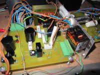
I attach a photograph of the supply, dismantled and taken out from chassis. I also attach the PCB layout that I used.
I attach a photograph of the supply, dismantled and taken out from chassis. I also attach the PCB layout that I used.
Attachments
OK, my bad, I understood the first time that you want me to connect the tubes to the +B also. If I am not wrong this time what you tell me to do is just disconnecting the elevated supply from the THINGY, put the signal valves into their respective sockets and check now the resistance between heaters (V+ or V- of the supply) and ground. The resistive value that I am measuring is 0.3 MegaOhms when the bottle with upper tubes is inserted into its socket. Without the tube it is 0.9 MegaOhms as I previously stated. I think that I forgot to say that I use a separate PCB for signal path and all these tests are realised without connecting it to the supply PCB, so the problem is on the supply side.
Any more ideas? Do you think the design is correct (I guess so because the only difference compared to the Morgan Jones one is that mine uses a non regulated tube rectifier for HT)? The resistance that I measured between both LT supplies can be due to capacitor charging as SY pointed out and it is relatively high. When I disconnect one LT supply from its reference (the emitter of MPSA42 in the case of the elevated supply and ground in the case of the non elevated supply) everything seems to work ok. I physically can't observe any obvious sign of interconnection between both supplies. They only share the LT transformer (each connected to a separate secondary) and a DPDT relay (each connected to a separate pole) that sets standby/on mode. I checked that transformer secondaries are completely DC isolated. I also desoldered relay to check that its poles are also isolated.
Did someone ever need 2 DC supplies to feed heaters in a SRPP/mu-follower stage? All designs that I saw managed to solve the issue with only one elevated supply from a potential divider directly from B+, so that it fulfills the maximum cathode to heater voltage in both valves and additionally the elevated voltage contributes to reduce hum in the lower tube.
Did someone ever need 2 DC supplies to feed heaters in a SRPP/mu-follower stage? All designs that I saw managed to solve the issue with only one elevated supply from a potential divider directly from B+, so that it fulfills the maximum cathode to heater voltage in both valves and additionally the elevated voltage contributes to reduce hum in the lower tube.
They are not supposed to be in this rectifier (in some others, for example, GZ34, they are), but with all of the relabeling, counterfeiting, and yes, even real stuff that's defective, it needs to be checked.
Those of us who eschew vacuum tubes for provision of DC don't face these problems.
Those of us who eschew vacuum tubes for provision of DC don't face these problems.
OK, thank you for your reply, Costis. I checked isolation (resistance) between EZ81 cathode and heater pins: the multimeter reading is open circuit, so the tube cathode is in perfect state and there is no wire or contact between cathode and heater. But I think the answer to this problem is on the line Costis was suggesting: I checked also the resistance betwen socket pins. The resistance between cathode pin and one heater terminal was like 10 MegaOhms, but the reading of resistance between cathode pin and the other heater pin (the nearest to the cathode pin) was like 50 kiloOhms. So the problem may be in the socket: I used flux to solder wires to the socket pins and I can see physically some remainder over cathode pin (flux may seeped internally). Taking measurements I sometimes observe a resistance about 2 MegaOhms between them, sometimes about 50 kiloOhms, so the problem should be that.
I'll have a look to try to solve that. Notice that the rectifier heater is NOT using the LT DC supplies, it is connected to a secondary of the HT transformer and directly AC heated (the reason of this is that the hungry EZ81 heater takes 1 A, which in addition of rest of consumption is much for the poor LT supplies), so I wonder if overcoming this would make the supplies work properly.
OK, the resistance between cathode and heater pins in the socket (tube removed from it) seems too be oscillating from 50 kiloOhms to 16 MegaOhms, so the problem should be around there. Eventually, when I turned it on again this morning I managed to get it to work perfectly for the first time, but my illusions went soon: now it is not working. I feel that the answer is closer.
I've been testing a little more this morning and I'm afraid that the cathode to heater resistance is not the reason of the problem. Before turning the supply on I measured the cathode to heater resistance and the reading was like 10 MegaOhms. The supply didn't work properly and behaved as previously described.
At least I corroborated that the design is correct because the supply worked once yestarday perfectly. If this were a RF/Microwave design I could find thousand of reasons to explain why it isn't working but this is just a DC supply. So a connection between lines in the board should be clearly observable if that is causing the issue and I couldn't find any in two weeks.
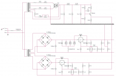
The only idea that is left on my chest is the following: there could be a problem with the relays that pre-heat the rectifier and switch on/standy the 750 Ohm resistors in regulators. Notice in the attached schematics that I used a separate relay for each task and the relay that switch on the HT supply is a bigger one. I used these ones: http://www.findernet.com/comuni/pdf/S30EN.pdf I checked them and isolation among their respective pins was perfect. Maybe they have difficulties to operate about 1 A AC current passing through the rectifier heater or ~220 volts DC of the elevated supply regulator. They can have leakage and/or switch not perfectly.
What do you think? Any other ideas?
At least I corroborated that the design is correct because the supply worked once yestarday perfectly. If this were a RF/Microwave design I could find thousand of reasons to explain why it isn't working but this is just a DC supply. So a connection between lines in the board should be clearly observable if that is causing the issue and I couldn't find any in two weeks.
The only idea that is left on my chest is the following: there could be a problem with the relays that pre-heat the rectifier and switch on/standy the 750 Ohm resistors in regulators. Notice in the attached schematics that I used a separate relay for each task and the relay that switch on the HT supply is a bigger one. I used these ones: http://www.findernet.com/comuni/pdf/S30EN.pdf I checked them and isolation among their respective pins was perfect. Maybe they have difficulties to operate about 1 A AC current passing through the rectifier heater or ~220 volts DC of the elevated supply regulator. They can have leakage and/or switch not perfectly.
What do you think? Any other ideas?
Attachments
- Status
- This old topic is closed. If you want to reopen this topic, contact a moderator using the "Report Post" button.
- Home
- Amplifiers
- Tubes / Valves
- Troubles when elevating a LT supply