Hi,
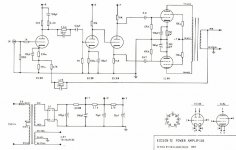
I wonder if anyone can answer some questions regarding this amplifier? It is an EL84 based amplifier run in pentode mode with feedback. It uses three ECC88 valves to provide the gain and driving/phase splitting. I am in the process of refurbishing the amp and do have a schematic but it is a little confusing. The amp sounds good but has very high gain and I notice that the mains transformer becomes extremely hot after using it for a while.
1. Conventionally in a valve power amp the feedback resistor is in parallel with a compensating capacitor. In this amp, however, there is a 4.7K feedback resistor in series with another 4.7K feedback resistor and the 270pF (220 pF in the schematic) compensating capacitor is in parallel with only ONE of the feedback resistors. Why is this?
2. In the schematic there is a 2.2K resistor in series with a capacitor and both are in parallel with the anode resistor of the input valve. Presumably this is to provide additional compensation. However this resistor is missing on the actual circuit. Instead there is a 270 pF capacitor (not shown on the schematic), just after a 1K grid stopper, from the grid of the input valve to ground. Is this to provide low pass filtering and does it replace the action of the additional compensation?
3. I have decided to apply some high pass filtering at the input of the amp since I suspect the output transformers are saturating at low frequencies (flabby bass). I also want to reduce the gain of the amp by using a resistor ladder network at the input. Would all these resistor cap combinations cause horrible phase shifts?
I hope someone can help.
harlequin
it does appear to be a bit of an oddball design. i am not surprised there is too much gain...there are too many valves to drive a pair of EL84s! also there is that 1M5 resistor bypassed by 22nF feeding the second gain stage...that will give a treble boost. how old is this design and what was it used for? If I where you i would bypass the first ECC88. connect your input directly to the second and connect the feedback to that valve's cathode. you'll probably have to fiddle with the values feedback series resistor and it's paralleled capacitor. If the power transformer is getting hot its probably just a bit small - the Dynaco power tarnnies always seemed at the edge of meltdown as well.
Nothing oddball with this one!
This is from famous Audion and Audio Innovations designer Erik Andersson. The reason for the high gain was that it should be used with a passive preamp. This was called Edison 1 and had a good RIAA stage together with the passive line.
Very good special design OPTs.
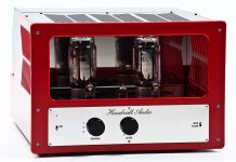
This is Eriks latest:
This is from famous Audion and Audio Innovations designer Erik Andersson. The reason for the high gain was that it should be used with a passive preamp. This was called Edison 1 and had a good RIAA stage together with the passive line.
Very good special design OPTs.
This is Eriks latest:
Attachments
Last edited:
if he designed audionote and audion amps i am sure he knows what he is doing! and thus i doubt the OPTs would be inadequate. just slap a volume pot on the input then. this amp having so much gain is not suited to be used with a preamp (if that is what you are doing). if you want to roll off the bass the easiest way would be to make the coupling caps to the EL84s smaller - try 100nF and see how it sounds.
Hi,
I agree; here is the schematic for the amplifier. The coupling capacitors in my particular amp are all 0.68 uF, another difference from the schematic.
these coupling caps seem to be the reason for the bass issue. If you calculate the cutoff frequency, it is way too low. For example, the first to second stage is -3dB at 0.23 Hz! Replace them with the values on the schematic, even go lower. And yes, the "treble peaking" thing in that area is something out of a Marshall amplifier, odd..
Hi,
I wonder if anyone can answer some questions regarding this amplifier? It is an EL84 based amplifier run in pentode mode with feedback. It uses three ECC88 valves to provide the gain and driving/phase splitting. I am in the process of refurbishing the amp and do have a schematic but it is a little confusing. The amp sounds good but has very high gain and I notice that the mains transformer becomes extremely hot after using it for a while.
Pretty standard for a budget amplifier biased into class AB.
Gain is related to the nominal line level, passive its quite low.
1. Conventionally in a valve power amp the feedback resistor is in parallel with a compensating capacitor. In this amp, however, there is a 4.7K feedback resistor in series with another 4.7K feedback resistor and the 270pF (220 pF in the schematic) compensating capacitor is in parallel with only ONE of the feedback resistors. Why is this?
This is phase compensation of the overall closed loop, its not related to
the overall compensation of the amplifier which is applied to the open loop.
2. In the schematic there is a 2.2K resistor in series with a capacitor and both are in parallel with the anode resistor of the input valve. Presumably this is to provide additional compensation. However this resistor is missing on the actual circuit. Instead there is a 270 pF capacitor (not shown on the schematic), just after a 1K grid stopper, from the grid of the input valve to ground. Is this to provide low pass filtering and does it replace the action of the additional compensation?
3. I have decided to apply some high pass filtering at the input of the amp since I suspect the output transformers are saturating at low frequencies (flabby bass). I also want to reduce the gain of the amp by using a resistor ladder network at the input. Would all these resistor cap combinations cause horrible phase shifts?
FWIW you have to understand the overall compensation arrangements.
You can attenuate the input, or reduce the closed loop gain by playing
with the feedback resistors. The critical parameter is the gain margin.
(how much you can reduce feedback gain without stability issues)
I hope someone can help.
harlequin
rgds sreten.
Last edited:
The "treble peaking" is just another high pass filter and part of the phase compensation in the fb loop. The 3 dB point is well below audible so I don't know about the "treble" thing.
The value of the coupling caps is also part of the phase compensation and increasing the value to ,68u has probably put your amp on the limit to low freq oscillation, hence the flabby bass.
/Olof
The value of the coupling caps is also part of the phase compensation and increasing the value to ,68u has probably put your amp on the limit to low freq oscillation, hence the flabby bass.
/Olof
Some very helpful comments and suggestions, thanks.
I also have a few comments and observations regarding this amplifier. As revintage has stated this is an Erik Andersson design. He, I think, was also involved with the design of the Audio Innovations 1st Audio amp (a DHT 2A3 push pull amp) which I once owned and regret ever selling.
The Edison 12 amplifier was also supplied in kit form as the Hi-Fi Answers (HFA 12) amp. I even have the original review/test report from October 1988 Hi-Fi Choice magazine where they actually mention saturation at low frequencies. It was advertised as a pure class A design and it certainly gets pretty hot in use. I bought the amplifier quite recently and it certainly shows signs of being tampered with; some of the caps don't even match in value between L & R channels. I want to persevere with it though because it produces a very natural and vibrant sound quality.
I do use a "passive preamp", a DIY Pass Labs B1 buffer preamp but I still find the gain far too high. Using sensitive speakers in a small room is probably the reason. I quite like jakruby's suggestion of bypassing the first ECC88 and connecting the feedback to the second valve. Incidentally the left and right channels are shared in the first valve but the second and third valves in the schematic are actually the two triode sections of the same valve.
If I was to bypass the first valve could I simply duplicate the circuit arrangement for that valve for the second valve? In which case should I include the 2.2k resistor in parallel with the anode resistor (shown in the schematic but absent from the actual circuit) and leave in the "treble peaking" filter?
I have actually seen a circuit modification for this amp where the first valve is bypassed but the feedback loop is disconnected and the EL84 valves are triode connected. I want to keep this as a pentode connected amp and so require the feedback loop.
I have also seen it mentioned, even by Andersson himself, that a limitation of the amplifier is the use of a single 4 section capacitor in the power supply. To reduce hum, which is quite high, he suggested replacing this with 4 discrete capacitors. I think I will try that and also possibly replace the 47 Ohm resistor (33 Ohm in the schematic) with a 1H choke to reduce ripple. Is this sensible?
Yes, thanks for the advice.
I considered using a choke from this supplier Bluebell Audio, the C-clamp 158T, which has a quoted resistance of 40 Ohms. It did strike me as quite a high resistance for a 1H choke.
I considered using a choke from this supplier Bluebell Audio, the C-clamp 158T, which has a quoted resistance of 40 Ohms. It did strike me as quite a high resistance for a 1H choke.
I quite like jakruby's suggestion of bypassing the first ECC88 and connecting the feedback to the second valve.If I was to bypass the first valve could I simply duplicate the circuit arrangement for that valve for the second valve? In which case should I include the 2.2k resistor in parallel with the anode resistor (shown in the schematic but absent from the actual circuit) and leave in the "treble peaking" filter?QUOTE] Duplicate the grid and cathode circuits of the first valve for the second valve. DC couple from the anode of the first valve to the grid of the third valve, deleting the 1.5M & 22nF. IMPORTANT. Swap the output transformer yellow and orange leads, this will correct the phase. If you have HF stability problems, add the 2K2 and 100pF to the anode of the first valve, you could also add 5pF in parallel to the 220k input resistor.
Hi,
FWIW bypassing open loop sections will not reduce the closed loop gain.
This will still be the same, all you will do is reduce open loop gain, you
might increase the gain margin, depends on which stage is critical.
But its basically not a good idea, assume the designer is correct.
Simply put an attenuator at the input, or reduce the feedback ratio, or both.
Reducing gain with more feedback will give tighter bass amongst other things.
FWIW reducing the gain by increasing feedback will make all things better,
output impedance, distortion, gain accuracy etc, but don't overdo it, as
you can run into stability issues. FWIW increased coupling capacitors do
not create low frequency stability issues, the number of them matters.
Again FWIW going from a CRC supply to a CLC supply is usually a good
idea but the choke resistance should be similar to the resistance value.
(Capacitors maintain peak voltage, inductors average it, but need current.)
rgds, sreten.
Last edited:
Hi,
I see. So basically my best options would be to EITHER triode connect
the EL84's, bypass the input stage, and remove the feedback OR leave
the amplifier as it is and apply some attenuation at the input.
Hi, IMO of the two options the latter is the one that will work, rgds, sreten.
(Your best option is IMO increasing compensation and reducing closed loop gain.)
Hi,
That Edison 12 power amp has a high input impedance, greater than 200 kOhm, so the choice of potentiometer value isn't too critical. I used a 50 kOhm potentiometer (maximum output impedance of pot ~12.5 kOhm) with no problems and this also makes it an easy load for your source. I would only be concerned if your source output impedance is abnormally high and/or you use long high capacitance interconnect cables.
I recommend a Noble, Alps or Tocos potentiometer.
Regards
harlequin
The potentiometer used in Edison One - the passive preamp that was sold together with the Edison 12 - was rated at 100k.
However, the designer of the amp has later stated that it was a mistake to do this. He recommends this redesigned Edison One which uses a buffer stage between the volume control and the power amp.

And here's the original Edison One schematic. http://i.imgur.com/nEYKyG1.gif
However, the designer of the amp has later stated that it was a mistake to do this. He recommends this redesigned Edison One which uses a buffer stage between the volume control and the power amp.
And here's the original Edison One schematic. http://i.imgur.com/nEYKyG1.gif
Last edited:
- Status
- This old topic is closed. If you want to reopen this topic, contact a moderator using the "Report Post" button.
- Home
- Amplifiers
- Tubes / Valves
- Edison 12 amplifier