Hi Ale.
Thank you for your answer. I am on holidays for 10 days. I thought to order mosfets before going to holidays. I will order when i am back. After testing filament regulator with dummy load everything goes fine and therefore i put 4p1l tubes in and everything went fine. After connecting gyrators tubes get warm and voltage drop on 10r vas 120 and 150mV so i turned both trimers. One chanel was ok and bias was set to 300mV or 30ma. But second chanell start to fluctating current and died. Tubes was cold after another startup...i got 67v on anode not 300V. That value is B+ and was first 260V than 280 now 300V aftet both channels are dead.
Thank you for your answer. I am on holidays for 10 days. I thought to order mosfets before going to holidays. I will order when i am back. After testing filament regulator with dummy load everything goes fine and therefore i put 4p1l tubes in and everything went fine. After connecting gyrators tubes get warm and voltage drop on 10r vas 120 and 150mV so i turned both trimers. One chanel was ok and bias was set to 300mV or 30ma. But second chanell start to fluctating current and died. Tubes was cold after another startup...i got 67v on anode not 300V. That value is B+ and was first 260V than 280 now 300V aftet both channels are dead.
You will kill 4P1L with 300V, especially if you don't use enough (few hundred Ohm) resistor to tie up G2 to anode.
The suspected -trioded- operating point (Ua, Ia) at -8V bias at about 150V, 28..30mA, WITH 150V on second grid.
At 220V anode voltage (about 32mA anode current), the dissipation is at the border, over it the tube would be over-dissipating.
Unnecessary to use this large B+ (with -8V bias), 220V is more than enough.
If you don't want to change power supply, try to use safer bias, for example -10V, and larger (even 1k) resistor for G2_to_anode.
You will kill 4P1L with 300V, especially if you don't use enough (few hundred Ohm) resistor to tie up G2 to anode.
No. When I experimented with 4P1L tubes in triode mode (g2+g3+anode), I got 11W dissipation on 300V B+. Even when it was higher and anode started glowing, G2 nor G3 were still not glowing. I see no point in any resistors.
Last edited:
I will say in another words... Before gyrator i have 300V on output 67V and no current, instead 140...150V and 30ma so tubes can not be damaged. And dissipation on drop resistors are 60ma 60v drop... less than 4W. Raw sulply that I have used is diodes- 470uf- 50ohm choke- 470uf- 1kohm-47uf plus 3.3uf mkp this goes to B+ on gyrator.
Last edited:
No. When I experimented with 4P1L tubes in triode mode (g2+g3+anode), I got 11W dissipation on 300V B+. Even when it was higher and anode started glowing, G2 nor G3 were still not glowing. I see no point in any resistors.
Once I tried 4P1L G2 as anode, and changed CCS to large -low DCR, below 50R- plate choke, I forgot that B+ was about 280-300V.
Tube defected, -G2 was melted? (about 40-50mA?)- after a minute.
After it, I don't use this tube without grid stopper resistors and with large B+.
I will say in another words... Before gyrator i have 300V on output 67V and no current, instead 140...150V and 30ma so tubes can not be damaged. And dissipation on drop resistors are 60ma 60v drop... less than 4W. Raw sulply that I have used is diodes- 470uf- 50ohm choke- 470uf- 1kohm-47uf plus 3.3uf mkp this goes to B+ on gyrator.
Are you sure, that grid resistor (to ground) inserted correctly?
No. When I experimented with 4P1L tubes in triode mode (g2+g3+anode), I got 11W dissipation on 300V B+. Even when it was higher and anode started glowing, G2 nor G3 were still not glowing. I see no point in any resistors.
I run my 4P1L PSE amplifier for some time at similar stress conditions. After 1-2 hours of playing, the valves started to develop a minor hiss noise which was gone when they cooled off. Running same valves cooler didn't present this issue. I even found some valves which will also run away a bit. After all these tests I decided to run them cooler
Today i changed bsh111 to another pair... at start everything ok after 1 min one channel start making problems...bias jump to 60mA and plate voltage to 180V... turning poti brings no change in bias setting after few minutes dead. and after 10 min another channel. I got B+245V... bias was around 29mA, on plate was 150V, but on Gate of bsh111 was 90..95V??? so on one side of 10Mohm resistor was 90V on other side 160V and i think that 60-70V Vgs killed the bsh111. Any idea what is wrong.
I run my 4P1L PSE amplifier for some time at similar stress conditions. After 1-2 hours of playing, the valves started to develop a minor hiss noise which was gone when they cooled off. Running same valves cooler didn't present this issue. I even found some valves which will also run away a bit. After all these tests I decided to run them cooler
My point was about dissipation by G2 and G3 without any extra resistors.
Today i changed bsh111 to another pair... at start everything ok after 1 min one channel start making problems...bias jump to 60mA and plate voltage to 180V... turning poti brings no change in bias setting after few minutes dead. and after 10 min another channel. I got B+245V... bias was around 29mA, on plate was 150V, but on Gate of bsh111 was 90..95V??? so on one side of 10Mohm resistor was 90V on other side 160V and i think that 60-70V Vgs killed the bsh111. Any idea what is wrong.
Ale may be on the road - but maybe I can suggest something to check.
The fact that your board was OK, then went wrong slowly suggests one thing to me - leakage.
10MΩ resistors (and the FET that connects to them) need a lot of care with soldering, to avoid leakage.
0. If your 10MΩ resistor drops 65V, that only takes 6.5µA to do. So we have to control surface-leakage current carefully. The PCB area must be very clean! Isopropyl alcohol (IPA) is the best agent for cleaning boards.
1. Please try to avoid solder with standard flux - this leaks very badly, and gets worse with time. It absorbs airborne moisture. Cleaning under SOT23 packages is hard to achieve, so it is best to avoid this contamination taking place.
Some of the old types of aggressive fluxes (e.g. found in «NOS» solder) can make a 5KΩ appear to be leaky.
2. Instead, please use « no-clean » solder. I like to use paste for SMDs, but you can use solder wire like 0.5mm Kristall-400 in a nice silver solder (Sn95.5 Ag 3.8 Cu 0.7). Artikel Nr. 810012 of Stannol GmbH.
Stannol Solder wires
3. Even with no-clean flux, removing visible deposits, and a wipe with IPA is good practice.
With the Gyrator PCB, only the node from the 10M resistor to the FET gate needs to be considered, but the board must be clean right up to the nearest trace, all of the way around it, including under packages of other devices.
Thanks Rod for chipping in, I'm travelling like crazy these days!
@androa76:
You shouldn't try measuring the voltage across gate and source. The reference voltage should be measured across R4. The BSH111BK has back to back protection diodes between gate and source.
1) Did you have in place the protection diode between drain and source on the BSH111BK?
2) Remove all MOSFETs - check them and should be shorted probably (IXTP08N100D or DN2540). Same with BSH111BK
3) test LND150 CCS and make sure you can set voltage across R4.
4) Check the drain source protection zener (D3) to check that is working as well
5) Refit top MOSFET and BSH111BK
6) Follow Rod's recommendation re flux cleaning
7) test again but with a dummy test load (4k7 10W)
You can post some pictures to see if we can identify anything else
hope this helps
thanks
ale
Hi Ale and Rod.
Both thanks for help.
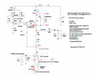
I changed BSH to JBF and now is working for 1hour ok but values are not ok. I havent put music trought preamp ...first static values must be solved.
In picture below are current test point values.
Flux is not a problem i always clean pcb with isopropanol and toothbrush.
IXTP haven*t been changed yet, LND150 are working ok because current can be set to specific value ...i set it to 25...26mA with JBF862
Both thanks for help.
I changed BSH to JBF and now is working for 1hour ok but values are not ok. I havent put music trought preamp ...first static values must be solved.
In picture below are current test point values.
Flux is not a problem i always clean pcb with isopropanol and toothbrush.
IXTP haven*t been changed yet, LND150 are working ok because current can be set to specific value ...i set it to 25...26mA with JBF862
Attachments
Last edited:
Ok 25mA but
BF862,215 NXP Semiconductors | Mouser Europe it is written 40mA
And at start i got 30mA because it was set for BSH and forgot to turn down the poti") .
.
BSH was soldered rotated because pins have other orientation. Sorri no picture now is JBF in that position. Any hints for testpoints... have talked to my friend who is also good with tubes and can be possible that my multimeter has lower impedance and is 72V not real value.
BF862,215 NXP Semiconductors | Mouser Europe it is written 40mA
And at start i got 30mA because it was set for BSH and forgot to turn down the poti
.BSH was soldered rotated because pins have other orientation. Sorri no picture now is JBF in that position. Any hints for testpoints... have talked to my friend who is also good with tubes and can be possible that my multimeter has lower impedance and is 72V not real value.
and can be possible that my multimeter has lower impedance and is 72V not real value.
No way.
DMMs have MOhm region AC input impedance.
DC resistance of DMMs mostly higher than AC impedance.
I have just finished my build of a 4p1l linestage/Dac-Output on a breadboard, so ugly like hell, but no hum, everything nice and quiet. Specs:
- Fully Balanced as the Ess9018 plays directly into the grids (50ohm I/V-Resistor, Dual Mono)
- Rod Coleman's regs
- LTP with Kevin-Carter Heat sink, 30mA perTube at 165V H+
- Loaded by LL1692A/PPAM
- currently tube rectified (one 5c3s) playing into one amorphous choke, than mundorf tub caps, than per channel one choke and another mundorf tub cap, so like first LC like 6H-100uF followed by 15H-200uF per channel (parts I had on hand), no regs or shunt tubes (yet)
So, a very simple LTP playing into a transformer. What do I hear:
- A very musical, transparent, delicate sound overall, it is more musical than my Unbalancer stage (The Unbalancer)
- At the same time, the holografic presentation is much different still: It is more blurred, diffuse some times, than again like wearing a headphone. I changed already once the phase by 180 degree as everything seem to be in front of the speaker thatn behind it, got better, but still very strange presentation.
So, I am not sure what is going on. The LL1692a plays currently in 1.75+1.75:1 Mode, so does a PP->SE conversion with foursecondaries in parallel...maybethis is where the blurr comes from ? This is my first transformer-coupled project, so not sure what to expect from an IT in general compared to RC...
Your experiences ?
I have as well Ale's boards here to test next, but maybe as well starting with balanced input and SE output like shown here mu stage fig.6 :
http://home.planet.nl/~rneervoo/mustage/figure6.gif
Best Regards
Last edited:
I just built a "simple" 4P1L line stage. Hammond 126B interstage used as plate choke with FT-3 teflon output caps. 30mA per 4P1L. Coleman regs, filament bias.
Sounds very good! Not quite my 01A with Ale's gyrator, but if you want a simple build this is a good way to achieve it. Drives my PSE 4P1L outputs nicely.
Sounds very good! Not quite my 01A with Ale's gyrator, but if you want a simple build this is a good way to achieve it. Drives my PSE 4P1L outputs nicely.
Attachments
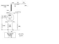
Interesting...why did you choose to use a coupling cap instead of th secondary of the IT ?
Is the connection of the suppression grid to the anode the common opion ? I have connected mine to the cathode...as recommended for other penthodes (like el34)...?
Best Regards
I've just followed the lead of others in connecting pins 2,3,4 together.
I have used both 126B and 126C from Hammond. I find that I get better sound just using these as a plate choke. In fact they're good as plate chokes. As an interstage I prefer LL1660.
I have some 126C left over from 26 experiments, and I'm going to try a pair with 2P29L at 15mA. Hoping for a good sound similar to 4P1L into 126B.
Yesterday i finally connected preamp, measure with scope...nice result almost square output at 100khz, no problem with sine wave,1-7,8V input output ratio with 50kohm poti. Very low noise level at max output. Tubes are still little microphonic if I tap at enclosure...but muuuch less than with regulated Smash DHT preamp which make noise even if you were touch selector knob and switch to other input. It is experimental version with not perfect material, we want to hear if it is good enough for making nice enclosure with hi-end material. It is worth... all will be better at end when all will be done as it must be. Also other 4p1l tubes will be tested. It was quite big difference when i was testing *original* Smash tubes with my pair of tubes. For that project i bought another pair that is now playing and can*t tell if they are better than mine, because my friend that ask me to do it for him, took it away from my workbench to his place and i didn*t have time to listen to it
I have some question about perfect GND connections... in next days i will make a picture.
Thank you all.
I have some question about perfect GND connections... in next days i will make a picture.
Thank you all.
- Home
- Amplifiers
- Tubes / Valves
- 4P1L DHT Line Stage