Depends if you use one transformer per winding or one for both. I just built an 01A filament supply for Ale's Gen 2 01A preamp. That used a 50VA 18+18v frame transformer and Hammond 159Y chokes for a 200mA filament supply at 15v.
For choke input you need to think about critical inductance. For supplies around 18v and a 4P1L at 620mA that would be roughly a 40mH choke. Hammond do a 159ZA at 300mH and 1A, and a 159ZC at 60mH and 2A. I use the 159ZC for 2x 4P1L outputs.
In terms of VA you have to do the calculations for what voltage supply you want at what current, and then multiply by around 2.
Last edited:
4P1L sellers?
Hi. I look for a reliable seller to get 4P1L tubes at decent prices. I made a search but some are "sold out" and other ask $8.00 each. On eBay, well, not sure...
I'm interested by Ale's boards for a line preamp. BTW he should give me an answer about that.
Thanks
Hi. I look for a reliable seller to get 4P1L tubes at decent prices. I made a search but some are "sold out" and other ask $8.00 each. On eBay, well, not sure...
I'm interested by Ale's boards for a line preamp. BTW he should give me an answer about that.
Thanks
Two units 7$00 USD
Tubo 4P1L RL2/4P6 2 piezas | eBay
Four units 17$00 USD
http://www.ebay.es/itm/4P1L-4LS1-RL2-4P6-RUSSIAN-TUBE-Same-Date-Code-1980-1983-Lot-of-4pcs-/182339198528?hash=item2a74435e40:g:ITUAAOSwXeJYGK6c
Tubo 4P1L RL2/4P6 2 piezas | eBay
Four units 17$00 USD
http://www.ebay.es/itm/4P1L-4LS1-RL2-4P6-RUSSIAN-TUBE-Same-Date-Code-1980-1983-Lot-of-4pcs-/182339198528?hash=item2a74435e40:g:ITUAAOSwXeJYGK6c
Last edited:
check your mailbox
PM sent
PM sent
Hi,
what is for you decent prices? And how many pcs do you need? I have a surplus on my private stock.
Hi. I look for a reliable seller to get 4P1L tubes at decent prices. I made a search but some are "sold out" and other ask $8.00 each. On eBay, well, not sure...
I'm interested by Ale's boards for a line preamp. BTW he should give me an answer about that.
Thanks
No affiliation and no commission, 4$ each.
http://www.diyaudio.com/forums/vendors-bazaar/240937-various-tubes-sale-20.html#post4877801
Thanks Felipe,
AndreyB found some (22) in Moscou at around $4.00 each. He sent me a pm this morning
Pierre
Good price.

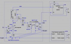
Hi Jim. As Béla pointed out, it's achievable but not ideal operating point. The issue you have may be due to the shunt regulator. For a Choke/OPT load that's ok, for the gyrator the shunt regulator may not like the load given it present a high impedance unless you bypass it as I recommended on the previous thread. I'd suggest you remove it completely. You don't need it for 2 reasons. Firstly, the gyrator will provide 100dB attenuation of the supply noise at least, secondly the voltage is set by the gyrator itself, no need of regulated HV.
Hope you can get it to work. Don't forget that in this configuration the 4P1L stage has 1-1.5Mhz bandwidth!
Cheers
Ale
Hope you can get it to work. Don't forget that in this configuration the 4P1L stage has 1-1.5Mhz bandwidth!
Cheers
Ale
Hi Jim. As Béla pointed out, it's achievable but not ideal operating point. The issue you have may be due to the shunt regulator. For a Choke/OPT load that's ok, for the gyrator the shunt regulator may not like the load given it present a high impedance unless you bypass it as I recommended on the previous thread. I'd suggest you remove it completely. You don't need it for 2 reasons. Firstly, the gyrator will provide 100dB attenuation of the supply noise at least, secondly the voltage is set by the gyrator itself, no need of regulated HV.
Hope you can get it to work. Don't forget that in this configuration the 4P1L stage has 1-1.5Mhz bandwidth!
Thanks Ale but I had already removed the shunt regulator. I guess I was not clear on my last post. Anyway I powered back up and was able to adjust the pot to achieve a perfect 25 ma! So I'd call this operator error on my part. Anode voltage is about 138 - 140 vdc so circuit is good. Sound is very good and dynamic except for a nasty ground loop hum that I need to sort out but I'm not sure it is worthwhile as the gain is way too much for my system. I can only advance my TVC about 3 notches now. And I can now what is meant by how microphonic the 4p1l can be. This was not an issue with the stepdown OT circuit and the gain was in line with what I need.
I am going to change over the 01a design this weekend.
Thanks for the help to you and Bela.
Jim
Hi Guys
I am a bit of a turtle on this and having started collecting parts for the Gen3 Siberian, have also shifted to collecting parts for recently acquired gyrator boards. So any advice, recommendations and experience from implementing this version gratefully received.
I think there is some good advice in this and the 01a thread already, but keen to hear others experiences and understand gain and potential implementation options with the classic S&B TVC.
Having acquired a handful of 4P1L's, I feel more comfortable with these well matched and plentiful tubes, than pursuit of the generally accepted better 01a and 10Y.
Thanks in advance.
Grantn
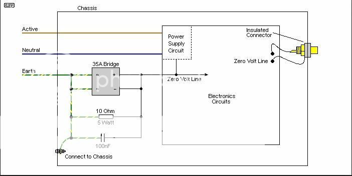
I'd like to know more how your grounds should be connected using the 4p1L with gyrator board when using a separate signal chassis and power supply chassis.
Right now I'm running 9 wires between the 2 chassis as follows:
2 wires (times 2) for rectified filament dc to Coleman filament regulators
2 wires B+ and ground (times 2) to the 2 gyrator board connections (grounds terminated at main star ground on power supply chassis)
1 wire for signal ground from signal chassis star ground to main star ground on power supply chassis. This includes wires from the 2 filament resistors and the 2 RCA input grounds.
The RCA output grounds which were not connected when using the output transformers are now routed back to the same star ground on the signal chassis. So this one point handles all grounds except the ground to the gyrator boards.
The above design works fine with the OT design with the exception that the RCA outputs are not connected obviously to star ground. It is very noisy however with the gyrator boards. I have a ground loop issue somewhere.
My system is simple. I have a source SACD/DAC to 4p1l chassis to TVC chassis to one of 3 different amps. All connections with unbalanced shielded RCA interconnects.
Jim
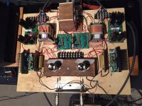
Here is picture of very messy signal board. Power supply not shown. The Lundahl outputs and shunt regulator are disconnected.
How to connect grounds is a good question, and maybe you can answer it with your breadboarding experiments.
The filament circuit isn't grounded until the output of the Coleman regs, so that's not an issue.
But how to connect the PSU and the input and output grounds, and the chassis earths on the PSU chassis (when separate) and the signal chassis is a good question. And where to put a ground lift if fitted
Thanks Ale but I had already removed the shunt regulator. I guess I was not clear on my last post. Anyway I powered back up and was able to adjust the pot to achieve a perfect 25 ma! So I'd call this operator error on my part. Anode voltage is about 138 - 140 vdc so circuit is good. Sound is very good and dynamic except for a nasty ground loop hum that I need to sort out but I'm not sure it is worthwhile as the gain is way too much for my system. I can only advance my TVC about 3 notches now. And I can now what is meant by how microphonic the 4p1l can be. This was not an issue with the stepdown OT circuit and the gain was in line with what I need.
I am going to change over the 01a design this weekend.
Thanks for the help to you and Bela.
Jim
Hi Jim,
I'm glad you worked it out. The 4P1L sounds brilliant. I guess you have a ground loop issue. The gain may be too much in that case you are better off with a step-down OPT.
The 01a will probably give you the same challenge as the gain is about the same.
Cheers
Ale
Hi Guys
I am a bit of a turtle on this and having started collecting parts for the Gen3 Siberian, have also shifted to collecting parts for recently acquired gyrator boards. So any advice, recommendations and experience from implementing this version gratefully received.
I think there is some good advice in this and the 01a thread already, but keen to hear others experiences and understand gain and potential implementation options with the classic S&B TVC.
Having acquired a handful of 4P1L's, I feel more comfortable with these well matched and plentiful tubes, than pursuit of the generally accepted better 01a and 10Y.
Thanks in advance.
Grantn
Hi Grantn
It will depend on your system and the amount of gain you need. There is plenty of info around here and the build is simple.
Personally I would:
1) keep power supplies on different chassis.
2) no need to regulate HT
3) pay special attention to the ground wiring
4) Use DC on the filaments, Rod Coleman regulators are the best in my experience
Cheers
Ale
Here is picture of very messy signal board. Power supply not shown. The Lundahl outputs and shunt regulator are disconnected.
Hi Jimmy,
The ground wiring is hard to follow but is a bit of a mess I think.
I would try to do the following:
1. Twist Coleman output into the filament and the filament resistor end.
2.I use a combination of star ground. First point is the input, with the grid leak resistor and the input connectors. I also place a ground lift switch at this point where it can help with ground loops. My gnd connection between GND and Earth is through a 10R/3W resistor bypassed with a 100nF cap. The second point of ground connection is the filament bias return. That is where you need to terminate the connection of the rod Coleman regulator. Then the next is the Gyrator PCB board and HT supply. Keep wires short where possible. Final connection is the output cap 510k resistor and output RCA connectors.
Hope this helps
Ale
However I would consider the safety risk of a large current surge through this type of connection. I use this type of ground lift, with the chassis (basically the two top plates and foil box lining) connected firmly to mains earth.My gnd connection between GND and Earth is through a 10R/3W resistor bypassed with a 100nF cap.
Ale

1 wire for signal ground from signal chassis star ground to main star ground on power supply chassis. This includes wires from the 2 filament resistors and the 2 RCA input grounds.
I never used this "extra" wire, IMHO it is the source of your ground loop.
Rod Coleman raw supply/supplies wires are floating, only connected to R.C. regulator.
R.C regulator output wires are connected to the tube filament and to the bias resistor's "ground" leg.
This point is the channel's ground point /or very close (few cm) to it/.
HT supply/supplies wires are connected individually to dual mono (left/right) channel B+ and negative supply point. In the simplest case (one tube preamp) the negative supply point is the channel's star ground point.
The input RCA's cold wire connected to first tube grid leak resistor "ground" leg.
The output RCA's cold wire connected to last tube's star ground point.
The channels star ground points connected together (main star ground point) and connected (or not) to chassis.
The HT supplies "cold" wires usually connected together in the PSU box, and grounded to PSU's chassis with R//C (as Ale wrote).....but sometimes I use "floating" HT supplies, and leave HT "cold" wires separately, don't connect its together /dual mono/, and don't connect to ground.
The safety earth (see Arkwardbydesign solution) circuit is important in the PSU box.
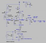
This append is my #26 preamp's simple connecting scheme.
Attachments
- Home
- Amplifiers
- Tubes / Valves
- 4P1L DHT Line Stage