I have had no issues, this is the third rebuild of this amp over the last six months and the same set of tubes have been in that position the whole time.
I was concerned about micro phonics but its only audible when switching volume due to the stepped attenuator so i dont consider it an issue. Just as well really as they dont fit into the enclosure standing upright.
I was concerned about micro phonics but its only audible when switching volume due to the stepped attenuator so i dont consider it an issue. Just as well really as they dont fit into the enclosure standing upright.
Hello,
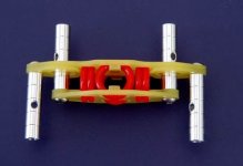
I was searching for some ideas how I could create a vibration isolation platform and I found some nice solutions in the drone world: damping plate.
A damping platform like that on some silentblock mounts should be very effective.
Regards,
Danny
I was searching for some ideas how I could create a vibration isolation platform and I found some nice solutions in the drone world: damping plate.
A damping platform like that on some silentblock mounts should be very effective.
Regards,
Danny
I found one that is very well designed and even the dimensions are perfect to put a loctal socket on it ")
Secraft vibration damper
Someone tested it in a drone and it was by a large margin the best.
Secraft vibration damper
Someone tested it in a drone and it was by a large margin the best.
Attachments
Last edited:
The only thing I'm not sure about with these ingenious vibration dampers - brilliant piece of research - is whether we need more mass directly under the socket. My approach has just been a lot of mass - 4mm aluminium top plate and massive chassis.
If the socket is unsupported by mass it could still respond to airborne vibration unless it's shielded. No problem shielding it since it doesn't get too hot in the input section. It does get hotter in the outputs.
If the socket is unsupported by mass it could still respond to airborne vibration unless it's shielded. No problem shielding it since it doesn't get too hot in the input section. It does get hotter in the outputs.
Hi,
Quick question. When it comes to cathode follower, is it worth the effort using such linear tube like Trioded 4P1L? Since it's 100% feedback, i wonder if a rather less linear tube say 6N8S would sound just the same. I'm thinking of having a line stage + channel selector but i don't need any gain.
Quick question. When it comes to cathode follower, is it worth the effort using such linear tube like Trioded 4P1L? Since it's 100% feedback, i wonder if a rather less linear tube say 6N8S would sound just the same. I'm thinking of having a line stage + channel selector but i don't need any gain.
The instructions are very detailed and will answer that question for you.
For example i'm using transformers with a 15v secondary into a 15mf/.68r/15mf supply, giving ~21v into the regulator under load. I could lower the voltage with a higher value resistor, but that should give you a ballpark idea.
P.S. when you work out the size of heatsink you need, make it bigger
For example i'm using transformers with a 15v secondary into a 15mf/.68r/15mf supply, giving ~21v into the regulator under load. I could lower the voltage with a higher value resistor, but that should give you a ballpark idea.
P.S. when you work out the size of heatsink you need, make it bigger
Ah yes. Found them. I just thought there was the raw dc supply doc and specific tube application notes. But there is a filament bias supply doc as well now.The instructions are very detailed and will answer that question for you
https://www.dropbox.com/s/pg34er1szexlebp/FilamentBias_Supply.pdf?dl=0
In the case of the V7 coleman regs it is 14v for the 4p1l.
Ah yes. Found them. I just thought there was the raw dc supply doc and specific tube application notes. But there is a filament bias supply doc as well now.
https://www.dropbox.com/s/pg34er1szexlebp/FilamentBias_Supply.pdf?dl=0
In the case of the V7 coleman regs it is 14v for the 4p1l.
Yes, Filament Bias works quite neatly - and the 26 and the 4P1L preamps both work well with a bias voltage of about 9V.
This made it easy to prepare a single document giving fully worked-out raw dc supplies with transformer types and Hammond part numbers, for anyone wanting to try Filament Bias. Separate PCBs to support the raw dc rectifiers & capacitors (etc) are here now, so there will be more documents, soon.
Cool!eparate PCBs to support the raw dc rectifiers & capacitors (etc) are here now, so there will be more documents, soon.
Just a heads up. In lieu of the hammond for the 4p1l filament bias setup. I ordered a 553-FS28-1300-C2 at mouser. 14v/2,6A dual bobbin type. Almost half the price of the Hammond 16 instead of 32 euros. The only drawback of the Triad is that it is a pcb mounted type and has no leadout wires like the Hammond. But that is a non-issue for me.
I used a couple of these in mine, Tamura PF24-30 Power Transformer 120/240 24VA Low Profile NEW | eBay rated for 15v @1.6a. As above they require mounting on PCB's.
Ooo very nice. I'd would have ordered a couple extra in a heartbeat if not for the shipping costs.I used a couple of these in mine, Tamura PF24-30 Power Transformer 120/240 24VA Low Profile NEW | eBay rated for 15v @1.6a. As above they require mounting on PCB's.
Sure - a massive chassis always helps. But I meant mass at the socket itself - attach the socket to a chunk of metal and then suspend it. Could be lead even - no idea what works best. It's just that a socket itself is very light.
By adding mass we lower the resonant frequency, optimally out of the audio domain. There's no larger excursion than at this frequency. However, there's another bug to fix as current carrying parts create their own magnetic field while moving around. Best is to tie down all components that should be fixated and only make supple connections to what has to move, like a suspended socket.
Hello!
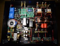
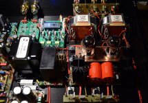
I am very pleased to announce that I have just finished my 4P1L preamp. ^^
The schematic is a little different - I did not use filament bias. Instead, I made creative use of the CCS in the SSHV2 to bias the tube. In my opinion, this arrangement has two advantages over filament bias: 1) the cathode resistor only dissipates 0.25W and can be of any type, and 2) this resistor is no longer in the signal path...
Indeed, the shunt element of the SSHV2 has its negative pole connected directly to the tube's cathode, acting like a huge ultrapath capacitor. There is no modulated current going through the cathode resistor, all of the audio signal loops in the shunt element, transformer and tube.
It works very well, this is the best sounding preamp I have ever built - dynamic and detailed, yet smooth and natural... I couldn't stop listening to it.
The 4P1L are biased at 20mA. I used a pair of LL1689 transformers because I already had them, but LL1660 should be slightly better.
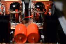
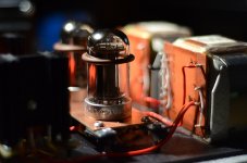
The tubes float on rubber suspensions - I have absolutely no problem with microphonic noises.
A pair of Rod's modules take care of the heaters.
The raw power supply is tube rectified and has a choke input followed by a big MKP capacitor.
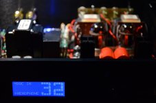
You may notice in the pictures a module hosting an Arduino Nano - it's a LDR volume and I/O controller that I've spent the last 9 months developing. It is IR remote and rotary encoder controlled and has a large 4x20 LCD screen displaying the current volume and the I/O channels' names. The I/O relays are best quality, latching. There can be up to 6 input and output channels. The digital part is completely isolated from the output, even the grounds.
This LDR volume controller works very well and sounds great. It does not need matched LDRs (the calibration is done by the software), the input impedance is customizable between 5K and 50K, and it has up to 80 attenuation steps.
-Vincent
I am very pleased to announce that I have just finished my 4P1L preamp. ^^
The schematic is a little different - I did not use filament bias. Instead, I made creative use of the CCS in the SSHV2 to bias the tube. In my opinion, this arrangement has two advantages over filament bias: 1) the cathode resistor only dissipates 0.25W and can be of any type, and 2) this resistor is no longer in the signal path...
Indeed, the shunt element of the SSHV2 has its negative pole connected directly to the tube's cathode, acting like a huge ultrapath capacitor. There is no modulated current going through the cathode resistor, all of the audio signal loops in the shunt element, transformer and tube.
It works very well, this is the best sounding preamp I have ever built - dynamic and detailed, yet smooth and natural... I couldn't stop listening to it.
The 4P1L are biased at 20mA. I used a pair of LL1689 transformers because I already had them, but LL1660 should be slightly better.
The tubes float on rubber suspensions - I have absolutely no problem with microphonic noises.
A pair of Rod's modules take care of the heaters.
The raw power supply is tube rectified and has a choke input followed by a big MKP capacitor.
You may notice in the pictures a module hosting an Arduino Nano - it's a LDR volume and I/O controller that I've spent the last 9 months developing. It is IR remote and rotary encoder controlled and has a large 4x20 LCD screen displaying the current volume and the I/O channels' names. The I/O relays are best quality, latching. There can be up to 6 input and output channels. The digital part is completely isolated from the output, even the grounds.
This LDR volume controller works very well and sounds great. It does not need matched LDRs (the calibration is done by the software), the input impedance is customizable between 5K and 50K, and it has up to 80 attenuation steps.
-Vincent
Attachments
- Home
- Amplifiers
- Tubes / Valves
- 4P1L DHT Line Stage