DHT are noisy, follows Rod & Disco advice, as we said it's very important short wire for PSU & regs & shielded wire for signal also keep as long as possible PSU for signal wiring and proper grounding, after proper wiring and grounding is possible that you need mechanical tube socket isolation.
The mechanical isolation ...i use the rubber isolator..no special problem with mikrofonic
merlin ..have you noise in your 4P1L pre ?
I haven't yet the 4P1L because now my #26 pre is sounding so nice but both are DHT and share the same microphonics issues.
What other noise sources do you have in the same room? Is it in a room with fluorescent lights, etc...? If so, turn those devices off and see if that helps.
Disco
I have just moved the pot close to input...not bad...the high freqence buzz get lower...not totally ..but lower
must hurry to build the pre in a better way
for now..thanks for all your help....now it is up to me to get it better
Best Bjarne
Yes, pay much attention to details when routing the wires and keep 'm short.
Also, it might be beneficial to break up the LV supply like this:
and move the noisy part outside the box.
Mind there's no ground connection before the filament supply.
What rectifier are you using, sand?
It's appropriate to have a large value at the consumer.
I'd make it 68uF-R-470uF-R--> <--470uF-Maida
Also, it might be beneficial to break up the LV supply like this:
An externally hosted image should be here but it was not working when we last tested it.
and move the noisy part outside the box.
Mind there's no ground connection before the filament supply.
After rectifire on high volt--resistor...470uf ---resistor ..470uf...resistor ..68uf...and close to Maida regulator 0.33uf
What rectifier are you using, sand?
It's appropriate to have a large value at the consumer.
I'd make it 68uF-R-470uF-R--> <--470uF-Maida
Last edited:
Bjarne,
It looks then that your 4P1L isn't oscillating. You clearly have a ground loop(s) or induced hum at some point in the circuit. However, it will be extremely hard at this point for everyone else to continue providing further advice unless you can draw your actual/real implementation. You can follow Rod's schematic with actual star grounding layout. Just pick up a piece of paper and draw. Then scan it and post it here, as simple as that. It can help big time, otherwise you will continue to make changes and perhaps we all can't see the elephant in the room")
Cheers,
Ale
It looks then that your 4P1L isn't oscillating. You clearly have a ground loop(s) or induced hum at some point in the circuit. However, it will be extremely hard at this point for everyone else to continue providing further advice unless you can draw your actual/real implementation. You can follow Rod's schematic with actual star grounding layout. Just pick up a piece of paper and draw. Then scan it and post it here, as simple as that. It can help big time, otherwise you will continue to make changes and perhaps we all can't see the elephant in the room
Cheers,
Ale
I'm waiting for my shipment. While collecting info, I stumbled upon Weird pentode connections thread that got me thinking, since the 4P1L max screen current is rated at 10mA, there is a viable option to operate it as a true triode by taking output from G2. Both G3 and Anode are grounded and act as a shield. By selecting Ig2 bias at ~5mA, we can readily use the chokes and other loads suitable for the #26. The prospect to be able to listen to a wire anode really picked my curiosity, it may share some sonic signature to the mesh plates, or even a uniquely different signature altogether. Any experience, comments or pitfalls to avoid?
Hi Indra,
I've done my homework at last, and I think we have a real winner here. I'd run it at 8mA if possible, but surely the 4P1L will beat a 26 in this mode
Here are the curves and SPICE model I developed.
Let me know how you get on!
cheers
Ale
Here is a slight variation on the theme that might be of interest.
http://www.diyaudio.com/forums/tubes-valves/102352-6v6-line-preamp-14.html#post1773726
best
tim
http://www.diyaudio.com/forums/tubes-valves/102352-6v6-line-preamp-14.html#post1773726
best
tim
If gain over 10 is needed in a DHT stage, then two options are to be considered. One is 4P1L as pentode
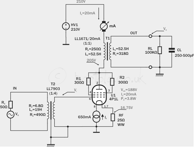
You can swing the 4P1L to 200Vpp easily with less than 0.3% THD. Nice harmonic distribution as well.
I tried the LL1671 in 1:1 and the LL2746 in 1:2 step-up. The latter can perform much better if wired in 1:1 (recommended by Thomas Mayer from his own designs):
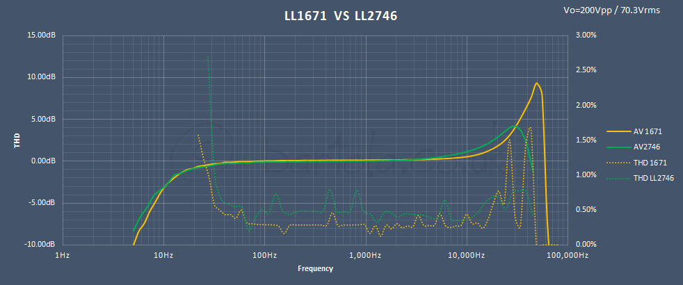
Obviously you can see I didn't bother to add Zobel compensation for the HF peaks above. Practical experience shows that you may even not hear the difference
Ale
Hi Ale.
What is the "function" of R1,R2 on 300 Ohm exactly.
They wasn't present when I build my Ver 1..
I have a few "clicks" from my 4P1L throught my Speakers quite randomly.
I'm going to change my cathode resistor to a non magnetic type..
I'm currently using Vishay-Dale 10W, and in generel I'm very satisfied with
my amp, so I'm no into any "big" update right now
I thought I will give the Mills MRA-12 a try.
http://www.hificollective.co.uk/pdf/pg16prn.pdf
/Thanks Michael.
Bjarne,
Use my 4P1L Line Amp basic schematic. Wire the internal grounds like this.
Connect the Ground "Star point" to chassis near the input terminals.
Don't use chassis as a "wire" to connect things together!
Try to make the input wiring very short (input socket near the volume control, and near the 4P1L socket) or used shielded internal wiring.
You must find the reason why the output trafo caused such buzzing - maybe the high voltage supply has noise......
Hi Rod...
Very Nice wiring schematic, I can see I was missing something.
The Rsn on 100 Ohm what is the wattage rating on this ???
/Thanks Michael.
Hi Rod...
Very Nice wiring schematic, I can see I was missing something.
The Rsn on 100 Ohm what is the wattage rating on this ???
/Thanks Michael.
Hi Michael,
Thank you - Yes, Rsn should be 0,5W rated. Carbon composition type is best, even a cheap 5% type.
Rsn and Csn form a "snubber" network. applied across the secondary of a transformer, they soak up nasty transient pulses caused by the leakage-inductance of the transformer. When the rectifiers stop conducting during each mains cycle, the leakage-inductance forces a big, fast pulse to appear. This can couple into your signal circuits (by conduction, or radiation).
Csn conducts the pulse into Rsn, which turns it safely into heat.
You can use a scope to tweek the values if you are searching for perfection (look for the slopes and pulse heights to be minimised); but the usual values work well for most trafos.
Csn conducts the pulse into Rsn, which turns it safely into heat.
You can use a scope to tweek the values if you are searching for perfection (look for the slopes and pulse heights to be minimised); but the usual values work well for most trafos.
Rsn and Csn form a "snubber" network. applied across the secondary of a transformer, they soak up nasty transient pulses caused by the leakage-inductance of the transformer. When the rectifiers stop conducting during each mains cycle, the leakage-inductance forces a big, fast pulse to appear. This can couple into your signal circuits (by conduction, or radiation).
Csn conducts the pulse into Rsn, which turns it safely into heat.
You can use a scope to tweek the values if you are searching for perfection (look for the slopes and pulse heights to be minimised); but the usual values work well for most trafos.
Hi Rod...
Thanks for your excellent explanation as usual.
Are you using a "Film Capacitors" for the 47nF, or do you have something
else here ???...
I have some "clicks" in my 4P1L , get worse when i tried the K75-10 pio russian caps in combination with my Vcap- CuFt.
With a Clarity MR and my belowed Vcap it was less frequent.
I'm close to make an order from mouser, so I thought of buying some WIMA MKS4 47nf , and some no magnetic resistor for the cathode.
I still on Ale version 1, using a 8 Ohm / 10 watt Vishay Dale "black" for the cathode resistor...
And again I'm very very satisfied with the "sound" of my 4P1L.
/Michael
Last edited:
- Home
- Amplifiers
- Tubes / Valves
- 4P1L DHT Line Stage