Step by step...
1.) is input voltage (for example 1VAC/1kHz) of two channels are equal?
2.) is output voltage of first stages -C1 "left" leg- are equal?
3.) is input voltage of two output tube's grids are equal?
4.) is anode and second grid voltages are equals?
5.) is each OPT UL tap equal? Typical error is swapping OPT's anode and HT taps.
6.) are you sure that each OPT wiring is 5k:8 ?
7.) is each OPT are equal?
Step by step...
1.) is input voltage (for example 1VAC/1kHz) of two channels are equal?
Input voltage at phono connectors is from the same signal generator, so they are equal.
Input voltage at grids of the two 6J9P are different by 1.5% due to input potentiometer error.
Input potientiometer is not shown on schematic.
2.) is output voltage of first stages -C1 "left" leg- are equal?
No, One channel is 1.77Vac and the other is 1.25Vac
DC bias point is the same +/-1.5V.
3.) is input voltage of two output tube's grids are equal?
Disparity as shown in 2 above.
4.) is anode and second grid voltages are equals?
DC values are Within +/-1.5V and reflect error in grid voltage bias adjustment (Single Turn Pots).
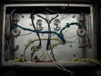
5.) is each OPT UL tap equal? Typical error is swapping OPT's anode and HT taps.
Color codes match, I didn't measure them to verify the transformers were built correctly.
See photograph for symetry of wiring.
6.) are you sure that each OPT wiring is 5k:8 ?
No. they are both 3.5K:8. Second build will use the 5K:8 transformers. I plan on comparing
amplifiers which are identical except the transformers.
7.) is each OPT are equal?
Both are from the same build, Edcor GXSE15-8-3.5K.
I will have to wait until tonight to make any more measurements.
1.) is input voltage (for example 1VAC/1kHz) of two channels are equal?
Input voltage at phono connectors is from the same signal generator, so they are equal.
Input voltage at grids of the two 6J9P are different by 1.5% due to input potentiometer error.
Input potientiometer is not shown on schematic.
2.) is output voltage of first stages -C1 "left" leg- are equal?
No, One channel is 1.77Vac and the other is 1.25Vac
DC bias point is the same +/-1.5V.
3.) is input voltage of two output tube's grids are equal?
Disparity as shown in 2 above.
4.) is anode and second grid voltages are equals?
DC values are Within +/-1.5V and reflect error in grid voltage bias adjustment (Single Turn Pots).
5.) is each OPT UL tap equal? Typical error is swapping OPT's anode and HT taps.
Color codes match, I didn't measure them to verify the transformers were built correctly.
See photograph for symetry of wiring.
6.) are you sure that each OPT wiring is 5k:8 ?
No. they are both 3.5K:8. Second build will use the 5K:8 transformers. I plan on comparing
amplifiers which are identical except the transformers.
7.) is each OPT are equal?
Both are from the same build, Edcor GXSE15-8-3.5K.
I will have to wait until tonight to make any more measurements.
2.) is output voltage of first stages -C1 "left" leg- are equal?
No, One channel is 1.77Vac and the other is 1.25Vac
There are no miracles.

Adiff= 20*log(1.77/1.25)
It's perfectly 3 dB.
1.) Is R1 100k in each channel? Measure it in power off state.
2.) Is V4 (1.1V) are equal in each channel?
3.) Is 3dB swapping if you swap U1 tubes?
Please measure in both channel:
U1(Vcathode)
U1(Vanode)
U1(Ianode on R16)
M1(Vdrain)
M1(Vsource)
M1(Vgate on D1 cathode).
1.) Is R1 100k in each channel? Measure it in power off state.
This is actually a 1M resistor from the wiper to ground, and a 100K pot on the input.
Left 96K Right 95.7K
2.) Is V4 (1.1V) are equal in each channel?
Left 1.173 Right 1.180
3.) Is 3dB swapping if you swap U1 tubes?
No.
Please measure in both channel:
U1(Vcathode)
Left 1.173 Right 1.180
U1(Vanode)
Left 138.5 Right 135.3
U1(Ianode on R16)
Left 138.5 Right 135.3
M1(Vdrain)
Left 220.4 Right 220.9
M1(Vsource)
Left 166.0 Right 165.8
M1(Vgate on D1 cathode).
Left 158.9 Right 158.4
U1(Ianode on R16)
Left 138.5 Right 135.3
1.) Ianode = Voltage on R16 divided by R16 value.
In 135-140V region at about 1.15-1.2V grid voltage the 6Ж9П (E180F) g2 current is about 4mA and anode current is about 5mA, thus current via R16 about 9mA.
--------------
2.) Is g3 connected to anode (or cathode) in both channels?
3.) Is both cathodes connected together in both channels?
-------------
4.) Is g2 to anode 470R (I use only 100R with E180F/E280F/D3a) resistor (4mA current flowing there) equal in both channels?
U1(g2) voltage (on the tubes pin)?
---------------
5) Why do you use that large (10k) grid stopper for first tube?
6Ж9П is low capacitance tube.
-------
These voltages and currents are static parameters.
If they approximately equals, but FET's mu is significantly different, not sure that AC gain is equal in both channel.
(1) I don't understand the question. Or is t his just a statement.
(2) G3 (pin 8) is connected to cathode pin3 with a short wire.
(3) There is no wire from pin1 cathode to pin3 cathode.
(4) I will check the value tonight.
(5) 6Ж9П is wired as in Triode mode with screen connected to anode. Therefore the input capacitance is miller capacitance mu times Ci. The 10K resistor is used to help suppress RF pickup by forming a low-pass filter with Ci * mu. I have several TV and FM transmitters within 2 miles of my house and RFI is always a big problem.
Last night when I first turned on the amp, both channel traces overlapped on the oscilloscope. However, I left the bench for a couple of minutes and when I came back, there was about a 3dB difference.
I will test it again to be sure this is what happened. If so it may indicate a thermal issue with a component.
(1) I don't understand the question.
Measure voltage on the resistor (between two legs). If you know the resistance, the current through the resistor:
I=U/R
Last night when I first turned on the amp, both channel traces overlapped on the oscilloscope. However, I left the bench for a couple of minutes and when I came back, there was about a 3dB difference.
Are you aware that coolant sprays are available for troubleshooting this sort of failure?
It turns out that I didn't have "a component" that was the issue. It was more like a perfect storm of all tolerances skewing one channel vs the other channel.
I rewired the pot which had the largest error, and swapped a couple of components between channels. I now have tracking to less than 1dB error between the channels from full volume to about 1/4 from minimum volume of the knob position.
I rewired the pot which had the largest error, and swapped a couple of components between channels. I now have tracking to less than 1dB error between the channels from full volume to about 1/4 from minimum volume of the knob position.
Hum is less than 0.7mV with the volume at full and no input. FFT shows power supply peaks below -70dB from 1Vrms.
Hooked to my Heresy speakers I have to put my ear next to the speaker to hear slight hiss and crackle.
My son (better ears) listened to it a while today and declared it "pretty good" whatever that is.
I added zobels from anode to gnd on the output tubes as they tend to oscillate without them.
I'll put a mesh plate on the bottom to allow airflow and keep fingers out, burn it in for a couple of weeks and it will be ready.
Attachments
![DSCN2954[1].jpg](/community/data/attachments/540/540755-ac447c05251e06ba30166ce324a68328.jpg)
I'll put a mesh plate on the bottom to allow airflow and keep fingers out, burn it in for a couple of weeks and it will be ready.
Unrelated question, if I may: How do you treat the edges of cut metal mesh to make it safe for handling?
![DSCN2955[1].jpg](/community/data/attachments/543/543198-71c386a3038d894d43b37d5181503819.jpg)
- Status
- This old topic is closed. If you want to reopen this topic, contact a moderator using the "Report Post" button.
- Home
- Amplifiers
- Tubes / Valves
- Another SE amp design.