Hi all,
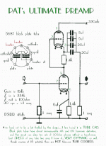
After I build my vext amp I plan on building a new pre to go with it. I thought about a mu stage using a 6SN7 since I have a few of these on hand. I'm also considering using the design below. Looking at the schematic and being familiar with the 5687 it looks like the values are wrong if these tubes are supposed to be running at "one third of their potential". These are capable of 30 mA (if you would want to push them that hard). If you drop 150 volts across a tube and run it at 10 mA then a 750 ohm cathode resistor is what you would want to use. In this design I would want to drop 165 volts across each tube (including the drop across the cathode resistor). The value of 1.4K (that is definately not a standard value) seems way too high. Also what would I gain by using that much capacitance in the coupling cap position if the input resistor of the next stage is 100K? The spec sheet for the 5687 can be found here:
http://www.diyparadise.com/5687.pdf
Maybe I'm missing something (not that that has ever happened before )
)
After I build my vext amp I plan on building a new pre to go with it. I thought about a mu stage using a 6SN7 since I have a few of these on hand. I'm also considering using the design below. Looking at the schematic and being familiar with the 5687 it looks like the values are wrong if these tubes are supposed to be running at "one third of their potential". These are capable of 30 mA (if you would want to push them that hard). If you drop 150 volts across a tube and run it at 10 mA then a 750 ohm cathode resistor is what you would want to use. In this design I would want to drop 165 volts across each tube (including the drop across the cathode resistor). The value of 1.4K (that is definately not a standard value) seems way too high. Also what would I gain by using that much capacitance in the coupling cap position if the input resistor of the next stage is 100K? The spec sheet for the 5687 can be found here:
http://www.diyparadise.com/5687.pdf
Maybe I'm missing something (not that that has ever happened before
Attachments
Regulator
Hi Gavin,
The PSRR for a SRPP is pretty poor . You could also use a ss voltage regulator which works very well. Even a capacitance multiplier will probably work very well. But if you really want to use a choke -------.
I have seen many people say that a choke filter 'sounds' better than a ss regulator . I really do not know as Ihave not made any comparison. I will do that one of these days.
Cheers.
Hi,
A 100K gridleak resistors does NOT necessarily mean a 100K Zin.
Caveat emptor,
Also what would I gain by using that much capacitance in the coupling cap position if the input resistor of the next stage is 100K?
A 100K gridleak resistors does NOT necessarily mean a 100K Zin.
Caveat emptor,
Hi Steve. Since the input resistor of the next stage is 100K I would say that the load on the circuit is going to be somewhere around 90K so obviously I can use a much lower value on the coupling cap. My real intention for posting the design is that the values seem all wrong to me and I wanted a second opinion. I think that the two cathode resistors should be around 750 - 820 ohms instead of the 1.4K shown. It really doesn't matter though. I like simple designs and since this circuit has a bad PSRR factor I'm not going to pursue it. If I can't make it sound good using a couple of healthy chokes in the PSU then I will look elsewhere. Hell I have a PCB layed out for a Mosfet power follower using a cascaded CCS. I may end up using that. It's meant to drive headphones but it would serve my purpose as a buffered volume control also.
Attachments
Hi,
Gavin,
They may seem unconventional but if you look at the 5687's curves you'll notice this will work too.
That's the beauty about valves, they may have a sweet spot that suits your application ( a preamp I gather) and than someone else optimises for a different service ( headphones) and decides for what values are best suited.
Loadlines do offer a lot of different dots...
My real intention for posting the design is that the values seem all wrong to me and I wanted a second opinion.
Gavin,
They may seem unconventional but if you look at the 5687's curves you'll notice this will work too.
That's the beauty about valves, they may have a sweet spot that suits your application ( a preamp I gather) and than someone else optimises for a different service ( headphones) and decides for what values are best suited.
Loadlines do offer a lot of different dots...
Hi,
You surely could.
Just make it a big well filtered supply and with the help of the chokes it will be great.
Just to tease you:
Cheers,
If I can't make it sound good using a couple of healthy chokes in the PSU then I will look elsewhere.
You surely could.
Just make it a big well filtered supply and with the help of the chokes it will be great.
Just to tease you:
Cheers,
Attachments
Hi,
I'd like to think so...
When I talk PS, I mean business...real business.
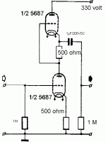
Either use well filtered, well regulated supplies ( my approach), or have a look at this brute force approach; yep, 6.000+ µF/400+ VDC.
Cheers,
SRPP preamp.
I assume that you would not post this unless you think it has a good chance of sounding good.
I'd like to think so...
When I talk PS, I mean business...real business.
Either use well filtered, well regulated supplies ( my approach), or have a look at this brute force approach; yep, 6.000+ µF/400+ VDC.
Cheers,
SRPP preamp.
Checked out
Gavin, you are right on. Downloaded the data for the 5687 tube and checked out. Cathode resistors should be approx 750 ohms for 10ma.
I wonder if/how the sound would change if the two "cathode" resistor values were changed, but kept the 10 ma flow? Or if the B+ were reduced?
Gavin, you are right on. Downloaded the data for the 5687 tube and checked out. Cathode resistors should be approx 750 ohms for 10ma.
I wonder if/how the sound would change if the two "cathode" resistor values were changed, but kept the 10 ma flow? Or if the B+ were reduced?
Hi,
Steve,
With all due respect...Either we opt for a SRPP circuit or a mu follower.
We can fiddle around with that no end but assuming Gavin is an amateur with little laboratory equipment to back up his findings he's going to experiment with resistor values no end.
I think I know what you're hinting at, from experience though I feel it's just another one of those half baked solutions that just isn't worth breaking your head over.
If I misread you, I apologise.
Cheers,
Might try varying the two cathode resistors to distribute voltages differently, or reduce the B+ and see how it sounds? Just an idea Gavin.
Steve,
With all due respect...Either we opt for a SRPP circuit or a mu follower.
We can fiddle around with that no end but assuming Gavin is an amateur with little laboratory equipment to back up his findings he's going to experiment with resistor values no end.
I think I know what you're hinting at, from experience though I feel it's just another one of those half baked solutions that just isn't worth breaking your head over.
If I misread you, I apologise.
Cheers,
listening purposes
Fdegrove, no offense taken. I was merely thinking if the supply wasn't built and the preamp wasn't for headphones, that one could try lower voltage B+ or by changing the voltage on the upper tube that:
1) raising the voltage on the upper tube would make it more of a constant current source because any changes from plate to cathode would be a lower percentage and visa versa
2) see if G could hear any sonic changes
3) If B+ could be lowered, the tube would probably last longer. But granted the 5687 is cheap in price.
Hi,
Sure...could do that too.
If you have years of experience you can probably pick a value for the intermediate R and optimise it by ear.
Still, I feel it's best to go through theory first and then decide which way to go.
If we want to stick to our twin triode SRPP then this is worth reading:
IMPROVED SRPP
Cheers,
- Status
- This old topic is closed. If you want to reopen this topic, contact a moderator using the "Report Post" button.
- Home
- Amplifiers
- Tubes / Valves
- Correct values for this schematic?


