I've built audio amps & a wide variety of electronics for many years, with & without surge suppressors. No problems at all either way. One monster had a measured surge of 400A from a 240V line.
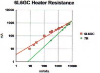
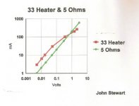
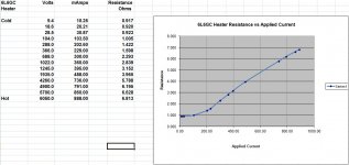
Beginning long ago while still working in a research lab I starting looking at the properties of various devices, not usually found on the data sheet. Some of that was the cold vs hot operating temperature. That included tube heaters such as the 6L6 & 33. I found the ratio to be in the order or 9-10, that is the heater had ~10X the resistance hot is it did cold. In many common consumer products the supply transformer limits that simply thru the benefit of a cheap build.
Later I looked at various semiconductors, incandescent lamps, LEDS & so on. All this information is worth knowing during the design phase. In later tube builds I included standby switches & measured both on & off line power real & reactive. And the harmonics back into the line. These in a residential area are nowhere near the problem all the other non-linear loads impose on the power system. For those unfamiliar, the 3rd, 9th & 15th harmonics are additive in the 3-phase source at some point in the power system. Both single & 3-phase transformers have to be sized to carry that excess current. Skin effect & proximity effect limit what the transformers can do, they must be oversized.
I've noticed many here on DIY talk on & on but often do nothing more than some simulations. Some threads seem to go on for a year with no hardware in sight. Not a good sign in my opinion.
Some might wonder who I am, check the BIO. And then the many articles on amplifiers & other devices in Glass Audio & AudioXpress magazines. While they were still published on paper.")
Attached a few examples of many. Most are on MS Spreadsheets. Ask!
Beginning long ago while still working in a research lab I starting looking at the properties of various devices, not usually found on the data sheet. Some of that was the cold vs hot operating temperature. That included tube heaters such as the 6L6 & 33. I found the ratio to be in the order or 9-10, that is the heater had ~10X the resistance hot is it did cold. In many common consumer products the supply transformer limits that simply thru the benefit of a cheap build.
Later I looked at various semiconductors, incandescent lamps, LEDS & so on. All this information is worth knowing during the design phase. In later tube builds I included standby switches & measured both on & off line power real & reactive. And the harmonics back into the line. These in a residential area are nowhere near the problem all the other non-linear loads impose on the power system. For those unfamiliar, the 3rd, 9th & 15th harmonics are additive in the 3-phase source at some point in the power system. Both single & 3-phase transformers have to be sized to carry that excess current. Skin effect & proximity effect limit what the transformers can do, they must be oversized.
I've noticed many here on DIY talk on & on but often do nothing more than some simulations. Some threads seem to go on for a year with no hardware in sight. Not a good sign in my opinion.
Some might wonder who I am, check the BIO. And then the many articles on amplifiers & other devices in Glass Audio & AudioXpress magazines. While they were still published on paper.
Attached a few examples of many. Most are on MS Spreadsheets. Ask!
Attachments
-
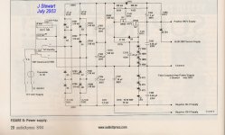 Figure 6 Power Supply Clone of Twin Coupled Amplifier w Caption.jpg271.2 KB · Views: 290
 -
 6L6GC Heater Resistance Log Plot.jpg52.6 KB · Views: 107
 -
 33 Heater & 5 Ohms 5W.jpg11.3 KB · Views: 86
 -
 Compare Lamps.jpg10.6 KB · Views: 69
 -
 Compare Power Diodes.jpg13.3 KB · Views: 75
 -
 Compare Pilots.jpg10.7 KB · Views: 89
 -
 33 Amp Hard Start w Caption & Photo.jpg181.9 KB · Views: 263
 -
 120 33 Amp F & T w Caption & Photo.jpg187.7 KB · Views: 268
 -
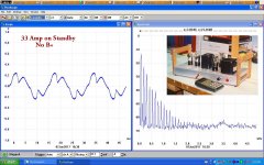 33 Amp on Standby No B+.jpg223.8 KB · Views: 257
 -
 6L6GC Heater Resistance Hot vs Cold B.jpg145.8 KB · Views: 301
For those unfamiliar, the 3rd, 9th & 15th harmonics are additive...snip
I'm no Prof, but I'm familiar enough to know this is true, for a Star connected 3 phase system
But in a Delta 3 phase system, the inverse is true.
Indeed I think that is much of the reason I see so many Star Delta transformers, periodically (besides that the other common use is for motors, and the Star Delta Tx isolates the Grid somewhat from noise injected back from 12 pulse rectifiers and the like.
Snip..... Skin effect & proximity effect limit what the transformers can do, they must be oversized.
Strictly at MV where I work, sub 33kV stuff - typically generation is designed to not be a harmonic mess at design stage.
I have seen many sub 50MVA generators tested and no single harmonic exceed single digit % at the trouble spots (3, 9, 15). Generally the "THD" is actually very good. Perhaps then it is the large step up to 132kV/400kV that are the real culprits
The things that do break these norms (such as other high order harmonics), are the trademark of Dc Dc investors and drives, with inadequate output filtering.
P.S. I would very much like some excel sheets, they looks useful indeed!
Back OT,
I've seen some pretty big MOVs explode, on some small amperage thyristor drives with frightening regularity, despite the correct fuse discrimination, and "idiot proofing".
I don't trust the things at all - any more than I trust tantalum at more than 25% of their voltage rating
Last edited:
I would very much like some excel sheets, they looks useful indeed!
--------------------------------
I will convert some of them to .jpgs so that they can be posted on DIY. But not immediately, lot of work here getting the place ready for winter.
I'll comment as well on the effect & uses of skin effect in large electric machines. I had quite a bit of 'hands on' early in my career. I had to sweat it out thru a ream of math that sorted out what is happening. The requirements for engineering status when I wended my way thru the system covered a lot of ground, some of which was a surprise to me. Foe example fluid mechanics. And ethics! What next! Somehow I made it!
Incandescent Lamp Tests
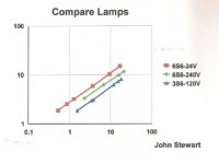
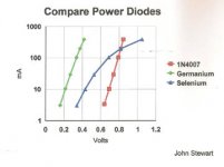
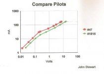
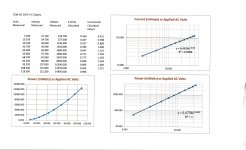
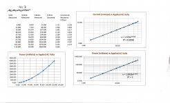
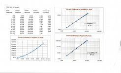
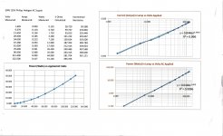
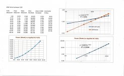
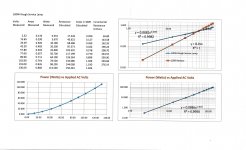
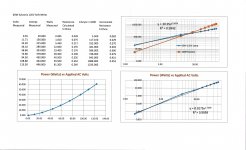
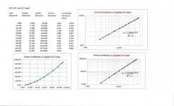
By popular (?) request here are some spreadsheets of the EI characteristics of common incandescent lamps. On a log-log scale, resistor plots have a slope of one. A square law device has a slope of two, a vacuum diode has a slope of 3/2. Tungsten incandescent lamp slopes are less than one, typically 0.45 -0.60. Their resistance increases as applied voltage is increased. The R2 value is an indication of how well the curve fits. An exponent close to one is good. Carbon filament lamps have a slope of one, thus same as a resister. But no spreadsheet in this group.
The lamps were run up by a Variac, voltage, current & in some cases power is measured using a pair of MetraHit 29S Precision DMMs & Wattmeter. The DMMs is built by elves in the Black Forest. Just Google for a description.
The 3S6 bulb was used in the Heathkit AG9 Bridged T Audio Oscillator. I built a clone circa 1956, it is still here on the shelf in working condition. I sub’d the 4C7, a 4W night light, the measurements of D% were the same.
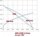
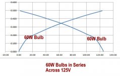
And what happens when a pair of incandescent bulbs are series connected, each is the others load resistor.
More later.
By popular (?) request here are some spreadsheets of the EI characteristics of common incandescent lamps. On a log-log scale, resistor plots have a slope of one. A square law device has a slope of two, a vacuum diode has a slope of 3/2. Tungsten incandescent lamp slopes are less than one, typically 0.45 -0.60. Their resistance increases as applied voltage is increased. The R2 value is an indication of how well the curve fits. An exponent close to one is good. Carbon filament lamps have a slope of one, thus same as a resister. But no spreadsheet in this group.
The lamps were run up by a Variac, voltage, current & in some cases power is measured using a pair of MetraHit 29S Precision DMMs & Wattmeter. The DMMs is built by elves in the Black Forest. Just Google for a description.
The 3S6 bulb was used in the Heathkit AG9 Bridged T Audio Oscillator. I built a clone circa 1956, it is still here on the shelf in working condition. I sub’d the 4C7, a 4W night light, the measurements of D% were the same.
And what happens when a pair of incandescent bulbs are series connected, each is the others load resistor.
More later.
Attachments
-
 Scan_0004.jpg364.5 KB · Views: 42
 -
 Scan_0003.jpg372.2 KB · Views: 42
 -
 Scan_0002.jpg400.1 KB · Views: 55
 -
 Scan_0001.jpg400.4 KB · Views: 57
 -
 Scan_0008.jpg375.4 KB · Views: 30
 -
 Scan_0007.jpg412.7 KB · Views: 35
 -
 Scan_0006.jpg408.7 KB · Views: 34
 -
 Scan_0005.jpg352.3 KB · Views: 50
 -
 60W & 40W in Series Across 120V w Captions & Trimmed.jpg57.9 KB · Views: 46
 -
 Two 60W Bulbs in Series Across 125V w Captions & Trimmed.jpg50.1 KB · Views: 46
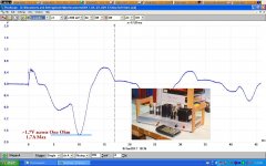
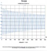
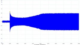
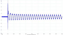
One of these is the first 1/2 second of a 2X6L6GC PP UL Amp. Built circa 1960. Still here on the shelf in working order. There are two for stereo. The front end is a pentode connected 6AU6 driving a paralleled 12AU7 phase splitter. The rectifier is a 5AR4. The PT is a Hammond 273Z. There is another trace somewhere shewing a longer time as the tubes begin conducting. Just gotta find it.
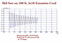
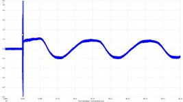
The other is a trace I did something like 20 yrs ago. I wondered what a Skil Saw did to the source while starting on the end of a 100 foot extension cord.
The other is a trace I did something like 20 yrs ago. I wondered what a Skil Saw did to the source while starting on the end of a 100 foot extension cord.
Attachments
I do. The "natural way of computing numbers" with a programming stick.How many people recognize the HP-67 calculator?
The first plot in post #89 indicates a heater winding turn-on surge ratio of 16A/2.4A = 6.7 for a set off cold valve heaters. That surge ratio will vary depending on a few factors. Factors include the valve line-up (as valve heaters can vary in their cold to hot resistance) and how much of the heater winding current rating is being used (ie. the heater winding voltage sag performance). Also the PT used in the test due to PT winding resistances and dynamic impedance, and the timing of the mains turn-on which can influence PT primary winding in-rush. There may also be some variation for amp design such as ss vs valve rectification, as an ss design will contribute its own turn-on surge current in the PT primary which may suppress the initial peak heater current level. As a ball-park range, the peak turn-on heater winding current is likely to be in the ratio range of 4 to 10x the continuous heater operating current.
Last edited:

As a ball-park range, the peak turn-on heater winding current is likely to be in the ratio range of 4 to 10x the continuous heater operating current.
I think most folks using NTC therms don't know where the ballpark is. For the typical value used to "protect" the tube heaters, the cold resistance is ~50R. That limits the start current through the PT primary to 2A @120v. But the turns ratio for the 6v heater winding is 20x so that would allow 40A of heater current.
For those with enough incentive, choosing an NTC can be done with a little more eye to detail, but it can get quite involved to go through all the design aspects so most eyes will glaze over and just a guesstimate for NTC model will be used.
If one is keen, an NTC in the mains primary can be selected based on the additive inrush contributions for PT primary magnetising current, reflected heater winding current, and reflected B+ supply current (if ss diode rectified). That can provide an estimate for total in-rush joules that the NTC has to cope with. The continuous max primary current also has to be known or measured, as the NTC has to have max continuous rating that copes (including some safety margin for the high end) and to ensure that primary current doesn't go below about 30% of NTC rating (otherwise NTC won't settle to a stable low resistance).
If one is keen, an NTC in the mains primary can be selected based on the additive inrush contributions for PT primary magnetising current, reflected heater winding current, and reflected B+ supply current (if ss diode rectified). That can provide an estimate for total in-rush joules that the NTC has to cope with. The continuous max primary current also has to be known or measured, as the NTC has to have max continuous rating that copes (including some safety margin for the high end) and to ensure that primary current doesn't go below about 30% of NTC rating (otherwise NTC won't settle to a stable low resistance).
Using SS rectifiers in tube amps brings B+ up immediately. I reasoned this was because filaments hadn't warmed up yet, so electrons weren't flowing- So no loads were present yet.
As sound appeared, B+ went from 420V to 368V. Largest filter cap is rated 450V- thought delaying B+ to filter cap was good idea to prevent 'no load' B+ from cycling to filter cap every startup.
Added amphenol CL-130 between rectifier diodes and filter caps, figuring it would slow inrush allowing filaments to heat up. Not much change- so added 2nd CL-130 in series. This lowered peak 420V to 405V- still not the target of 375-380V I was hoping for.
So will try different design-
Hooking a 6.3V filament winding to bridge rectifier, then to 6V DPDT relay through RC network. Should be fairly easy to find RC values to get desired delay time. Using 2 sets of contacts might help reduce arcing by dividing current, but adding shunt cap as mentioned makes sense so I might try that.
What concerns me is possible audible pop or buzz when relay is engaged, so maybe installing CL-130 in contacts circuit might help if that occurs?
Jim
Jim, the voltages in your PS are not stressing the first cap at all. The CL's are not providing any practical benefit unless you are using a very high first filter cap capacity value. Then the CL's might help protect your SS rectifiers if they are sub-rated for amperage value. If they are heavy enough you don't need the CL's. If the input cap is a common value used in SS duty like 50uf-100uf then there is no need for the CL's.
Using SS rectifiers in tube amps brings B+ up immediately. I reasoned this was because filaments hadn't warmed up yet, so electrons weren't flowing- So no loads were present yet.
As sound appeared, B+ went from 420V to 368V. Largest filter cap is rated 450V- thought delaying B+ to filter cap was good idea to prevent 'no load' B+ from cycling to filter cap every startup.
Added amphenol CL-130 between rectifier diodes and filter caps, figuring it would slow inrush allowing filaments to heat up. Not much change- so added 2nd CL-130 in series. This lowered peak 420V to 405V- still not the target of 375-380V I was hoping for.
So will try different design-
Hooking a 6.3V filament winding to bridge rectifier, then to 6V DPDT relay through RC network. Should be fairly easy to find RC values to get desired delay time. Using 2 sets of contacts might help reduce arcing by dividing current, but adding shunt cap as mentioned makes sense so I might try that.
What concerns me is possible audible pop or buzz when relay is engaged, so maybe installing CL-130 in contacts circuit might help if that occurs?
Jim
From my archives:
Transformer size is 250mA @ 240V and 2.2A @ 6.3V = ~ 74VA.
Power tubes take 12W Pa max and 2W g2 max which makes that the amplifier should not use more than about 40W (= 1/6A @ 240V).
But with the impulse of the solid state rectifiers charging of the capacitors the VA might be higher.
Filaments for 2 x EL84 and 1 x driver gives 1.82A.
The 6NO6 delay relay adds 0.3A, total 2.12A.
2.12A @ 6.3V = 13.36 Watt.
13.36 Watt (plus transformer losses) across 230V is at least 58mA. Try to reduce the initial surge through the filaments.
Steady state current for an NTC has to be between 0.3x and 1x of the steady state current.
The exact values of the NTC's vary a lot by manufacturer, e.g. some can take 500mA and others 1A for the same size / cold resistance.
If the correct values are assumed (!!!) (correct manufacturer and hence specifications) for the NTC's that are held:
Use a delay relay and 3 x 200 Ohm NTC resistors in series with the primary winding at startup.
When at 500 mA the 200D9 are 5 Ohm each, at 250 mA (60 watt) the resistance will be higher.
The NTC's take 32 seconds to fully warm up (but lose most of the resistance within seconds) and after 60 seconds get bypassed by the delay relay.
58mA across 600 Ohm (NTC at cold start) gives at least 35V voltage drop on the primary.
B+ at startup: (230 - 35) x 1.4142 = 276V.
The only question here is how fast the tubes heat up and how fast the NTC thermistors drop their resistance.
This limits the in-rush current and gives something of a slow start of B+ and especially the filaments will not flash up.
NTC's are necessary: If no NTC's are used in series with the primary winding then the driver cold B+ voltage exceeds maximum specification.
( The driver does not like a B+ (cold) > 300V (happens at switch on). EL84 are OK cold to 500VDC. )
Measure mains consumption and fuse 20% above this.
Turn On Surge vs Time
OK 20 to 20, Current vs time plots. But these are on the PT primary where we would normally install a current limiter.
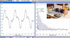
The amplifier in these tests is PP 6AQ5s driving a Hammond 1618 (10K P-P) I had built in 1957. It is nominally 8W. The driver is a 12AX7, one section connected as a normal triode driving the other as a split load phase inverter. The tone controls are a 6J6 connected in a Baxandall circuit. Positive FB in the 6J6 common cathode is avoided, the cathode is taken to common thru a silicon diode. A 12AX7 front end is corrected for a GE VR phono pickup, but for these tests that tube was left out. The PT is a Hammond 270BZ60 driving a 6X4 rectifier.
These single shot tests were done using a PicoScope 3224, 2-channel, 10 MHz scope. The time scales are different. The front end uses a 4 MHz Differential Probe to avoid ground loops. The sample is taken across a One Ohm resister on the low side of the line.
So we see the initial high current drift down as the tubes warm up. When the tubes begin conducting at about 20 seconds the current to the PT increases. Just as we would expect.
As Tim R has pointed out, the proper way to measure the initial current would require a way of switching on the supply at the point where the current would be the maximum. I’ve no way to do that, never built something to make it happen. I’ll leave that to one of the Eager Beavers here on DIY.
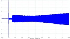
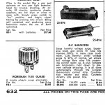
In Trace 0009 the startup is thru a Workman Tube Guard, a commercial current limiting device, common in the 1960s used as a surge suppressor for TV receivers. Looks like it still works.
How 'bout a I vs Time curve for tube heater with 6.3v applied?
OK 20 to 20, Current vs time plots. But these are on the PT primary where we would normally install a current limiter.
The amplifier in these tests is PP 6AQ5s driving a Hammond 1618 (10K P-P) I had built in 1957. It is nominally 8W. The driver is a 12AX7, one section connected as a normal triode driving the other as a split load phase inverter. The tone controls are a 6J6 connected in a Baxandall circuit. Positive FB in the 6J6 common cathode is avoided, the cathode is taken to common thru a silicon diode. A 12AX7 front end is corrected for a GE VR phono pickup, but for these tests that tube was left out. The PT is a Hammond 270BZ60 driving a 6X4 rectifier.
These single shot tests were done using a PicoScope 3224, 2-channel, 10 MHz scope. The time scales are different. The front end uses a 4 MHz Differential Probe to avoid ground loops. The sample is taken across a One Ohm resister on the low side of the line.
So we see the initial high current drift down as the tubes warm up. When the tubes begin conducting at about 20 seconds the current to the PT increases. Just as we would expect.
As Tim R has pointed out, the proper way to measure the initial current would require a way of switching on the supply at the point where the current would be the maximum. I’ve no way to do that, never built something to make it happen. I’ll leave that to one of the Eager Beavers here on DIY.
In Trace 0009 the startup is thru a Workman Tube Guard, a commercial current limiting device, common in the 1960s used as a surge suppressor for TV receivers. Looks like it still works.
Attachments
- Home
- Amplifiers
- Tubes / Valves
- NTC Thermistor As Soft Start For Tubes