I just re tubed & recapped a philco 49-1401 but one of the caps keeps blowing after about 15 minutes. It is cap C101. I did measure reverse voltage across it but it is connected exactly as schematic describes. I did use a normal wet electrolytic instead of a dry electrolitic that was in there originally. Would this make any difference? I will be glad to email schematic to anyone that would like to look at circuit. Thanks in advance.
Yes the old one was polarized I put in like the original.
That didn't work, need to use "advanced edit mode/manage attachments" and then be sure to actually upload the photograph.

Note that if you measured reverse voltage across that cap it is more than possible that the schematic symbol as drawn in your schematic is backwards. Or did you install (new) solid state rectifier diodes and put them in backwards?
Last edited:
Thanks for tip on attachments. The rectifier is a tube 50Y6GT . Since my last post I got a dry paper electrolitic & put in circuit & radio has played for an hour so far without cap blowing. I am concearned though because the reverse voltage has risen from -20 to -65 volts. I sure hope these type caps aren't flamable.
Make sure the plates of your rectifier tube aren't glowing. I once put the electrolytics in backwards in an old 1930's era Stewart-Warner radio set. The "tubes all lit up" (as they say on eBay) for about 15 minutes, but the radio still didn't play. It turned out I almost succeeded in melting the 5Y3! I have no idea why the electrolytics didn't blow...
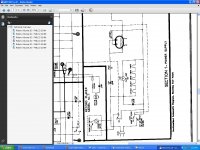
This appears to be a half wave voltage doubler and the cap appears to be oriented correctly in the schematic.
The voltage across that capacitor has a substantial AC component across it and a lot of cheap digital meters don't work properly under such conditions. The current through this cap is also significant in that not only does it have to cope with the ripple current, but also the entire load current of the radio it is powering on a continuous basis - a very demanding situation. A film capacitor (>= 400V rating) with a high continuous current rating might be a safer long term solution here.
Measure the voltage at the capacitor connected to the cathode of the other half of the rectifier that feeds the rest of the PSU. If this voltage is correct then the supply is working correctly.
Something else to note is that this radio/phonograph is line operated and is potentially extremely dangerous to work on. I strongly advised the use of an isolation transformer when troubleshooting this radio..
Last edited:
I do have a 10uf 600v poly on hand. Would that be sufficient since poly generally have superior characteristics to lytics in terms of esr & ripple?
Really needs to be 20uF as shown, voltage regulation and output voltage will be seriously impacted by the lower value, not withstanding better ESR, the reactance of a 10uF cap at 60Hz is twice as high.
For a low price (5 each) I found a couple of 10uf polys @ 400v I could parallel for 20uf at mouser .Each have 11 amp current rating. Would this be sufficent for long term reliability?
I think those ought to work pretty well if you have sufficient room.
Well I got in the poly today & they were just too large paralleled. Fortunately I found the problem. I studied the schematic from manufacturer but I couldn't make out some of the pin numbers on radio schematic so I went to a tube schematic from manufacturer. I found that pin 6 was unused on the tube but it had several components connected to it. It turns out that everything that was connected to pin 6 was supposed to be connected to pin 5 . What threw had me off was that pin 5 already had several components connected to it so it didn't look suspect.. I just shorted 5 & 6 and no longer blowing caps. All voltages normal except the 200 volt is around 225 which I suspect is due to my line voltage which is 122 instead of the 117 specd by the radio. Thanks for everyones input. This was my first experience with tubes & feel I know a little more about them now. I ended up with 2 35L6GT amp tubes. I hate for them to go to waste. Does anyone know a simple circuit for a small amp with these?Donald
- Status
- This old topic is closed. If you want to reopen this topic, contact a moderator using the "Report Post" button.
- Home
- Amplifiers
- Tubes / Valves
- Cap Problem with philco 49-1401