Hi Fellow tube-freaks,
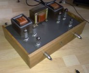
I'd like to present my latest creation, a PL84 push-pull amp.
Perhaps the most interesting thing is that I have tried to use the same output transformers before, with 807's in AB2.
Back then I could not get the wanted results without using gNFB (read: http://www.diyaudio.com/forums/tubes-valves/177754-plate-plate-feedback-measurements.html)
Now, I also connected the transformers secondaries to the cathodes of the PL84's.
This has been discussed on different threads here recently, and here: diytube.com :: View topic - Koren Local Hero and Mods
Responce is measured at 1Watt into 8ohms resistive load.
The nasty looking bode-plot is open-loop response.
Full output is more then 20 Watts (again into dummy load)
more pictures: PL84 push pull - My Photo Gallery
Any further suggestions?")
I'd like to present my latest creation, a PL84 push-pull amp.
Perhaps the most interesting thing is that I have tried to use the same output transformers before, with 807's in AB2.
Back then I could not get the wanted results without using gNFB (read: http://www.diyaudio.com/forums/tubes-valves/177754-plate-plate-feedback-measurements.html)
Now, I also connected the transformers secondaries to the cathodes of the PL84's.
This has been discussed on different threads here recently, and here: diytube.com :: View topic - Koren Local Hero and Mods
Responce is measured at 1Watt into 8ohms resistive load.
The nasty looking bode-plot is open-loop response.
Full output is more then 20 Watts (again into dummy load)
more pictures: PL84 push pull - My Photo Gallery
Any further suggestions?
Attachments
Thanks Tyimo,
I dont like to desribe sound. Sorry (I think it depends a lot on the speakers too.)
Lets just say it sounds perfectly good to me.
The plan is to build an RTP3C clone (Vacuum State - High End Hifi Equipment)
So i'll have balanced phono.
I also plan to build a balanced TDA1541a dac with a preamp stage similar to the RIAA stage in the RTP3C.
Later on, I might do the same thing to my reel-to-reel tape deck.
Yes, I plan to go fully balanced but have some work to do!
I tried sitting the cathodes in the output of the OPT like that once, it did sound fairly good but later I decided to take the OPT out of the feedback loop completely (I wrapped feedback around the driver+output tube to present the OPT with a low impedance drive, which sounded better).
Your use of the 16ohm and 4 ohms taps seem to give more feedback to one side than the other - 12 ohm output to the top and 4 ohm output to the bottom - is that supposed to be like that or should you connect the earth to the 8 ohm tap?
Your use of the 16ohm and 4 ohms taps seem to give more feedback to one side than the other - 12 ohm output to the top and 4 ohm output to the bottom - is that supposed to be like that or should you connect the earth to the 8 ohm tap?
I tried sitting the cathodes in the output of the OPT like that once, it did sound fairly good but later I decided to take the OPT out of the feedback loop completely (I wrapped feedback around the driver+output tube to present the OPT with a low impedance drive, which sounded better).
Your use of the 16ohm and 4 ohms taps seem to give more feedback to one side than the other - 12 ohm output to the top and 4 ohm output to the bottom - is that supposed to be like that or should you connect the earth to the 8 ohm tap?
4ohm + 4ohm on an OPT gives 16 ohms
You need to calculate with voltages, not impedances in this case.
This kind of feedback should give a better damping factor, now it depends if your speakers like that or not.
Newer speakers like it most of the time.
Congratulations, it looks nice. Looks alot like Broskie's Power Buffer that I've been wanting to build: Aikido Cathode Follower & More Triadtron
Not trying to shoot down your design. But I do see a conflict of sorts between the plate to plate local feedbacks and the CFB on the outputs. The Schade fdbk makes for a low Z load for the driver triodes, and the CFB makes for a large voltage swing requirement besides. I would try putting the Schade fdbk resistors back to the driver cathodes (with some resistance between them), and a CCS load on the driver plates. Then the driver triodes can develop the high voltage drive easily and linearly. May require some more input signal though.
Yes, that's my thinking anyway.
However, the RH series of SE amps work with a triode in the front loaded down by Schade feedback, and seem to be well liked. Apparently some 2nd Harmonic distortion cancellation occurs (in SE mode) between the driver and output there. For a P-P setup, this cancellation of 2nd H on each side could result in lower 3rd H in P-P. But one does not want to overdo it, higher harmonics likely spring up quickly.
If you have a sound card and FFT software setup, it might be illuminating to look at the distortion at the driver output and the final output. (sound cards need external resistive attenuation of the input test signals to 1 V or so for safety, and a cap to remove DC)
You mentioned a separate feedback winding on the OT. I'm guessing it has no center tap for easy balanced use. Could maybe put it end to end between the front end triode cathodes, with resistor tails off each end. But it may have too much voltage across it for the usual convenient input signal levels to drive. Just an idea.
hidnplayr... do you have the schematic of the power supply? Thanks.
I used simple mosfet series regulators to get the voltages needed (and this gives the advantage of being able to change the voltage easily).
B+ transformer was an isolation transformer that gives 230V sec.
I used chokes to reduce the voltage, they are ballasts from TL lamps
(for 18W/230V lamps = 5H)
I dont think you want to build an exact replica, do you?
Hi,
Schade feedback and a low Ri driver is a really bad idea. A high Ri triode in combination with an unbypassed cathode resistor works but with high distortion. As Smokingamp says distortion-cancellation helps, but it is still not the ideal solution.
You will get a lot better results if you do the Schade like an anode follower with a 15kohm resistor between the 88 anode and the 100k. Works better than any RH connected amp.
But again as SA says a combination of CFB and Schade is a conflict. Still the CFB in this case is extremely small so I doubt there will be a problem.
Last edited:
Hi,
Schade feedback and a low Ri driver is a really bad idea. A high Ri triode in combination with an unbypassed cathode resistor works but with high distortion. As Smokingamp says distortion-cancellation helps, but it is still not the ideal solution.
You will get a lot better results if you do the Schade like an anode follower with a 15kohm resistor between the 88 anode and the 100k. Works better than any RH connected amp.
But again as SA says a combination of CFB and Schade is a conflict. Still the CFB in this case is extremely small so I doubt there will be a problem.
My main concern is 3,5k together with 84´s. Working almost in Class-B you will of course get high power but this on the expense of sound quality.
This is an EL86, for which the 3.5K is more acceptable.
Shoog
Ha, we crossed when I edited my post
Why not concentrate on the text above instead or are you just picky today
You know we are in complete agreement here. It gets most people the EL86/PL84 thing
Shoog
I am interested in this because I built a PP EL86 amp which showed promise but kept blowing cathode CCS so I intend to decommission it.
I will rebuild using a 5687 LTP driving an interstage toroidal transformer in differential mode. The outputs will use garter bias with cathode to cathode bypassing. Using an interstage transformer will allow me to bias the EL86 grids to a negative voltage and hence allow the garter to work with minimal voltage loss. Should make a simple cheap little amp with the parts I have lying around.
Shoog
- Status
- This old topic is closed. If you want to reopen this topic, contact a moderator using the "Report Post" button.
- Home
- Amplifiers
- Tubes / Valves
- PL84/EL86 push pull