Hi,
I see what you mean now, that's by no means an autoxformer though.
Probably an S&B or Lundahl controlled by a rotary switch a la Shallcro or Elma 24 pos. or more, right?
IIRC, none of those are happy with DC on the input so I guess it's blocked somewhere.
No need to bother, I know these beasties...")
With Output Transformer.
Usually a small airgapped xformer to block DC and lower output Z at the same time.
Cheers,
I see what you mean now, that's by no means an autoxformer though.
Probably an S&B or Lundahl controlled by a rotary switch a la Shallcro or Elma 24 pos. or more, right?
IIRC, none of those are happy with DC on the input so I guess it's blocked somewhere.
I could ask Dave Slagle about this.
No need to bother, I know these beasties...
What's a WOT?
With Output Transformer.
Usually a small airgapped xformer to block DC and lower output Z at the same time.
Cheers,
Probably an S&B or Lundahl controlled by a rotary switch a la Shallcro or Elma 24 pos. or more, right?
Nope. S&B and Lundahl are transformers. The ones I have are autoformers, wound by Dave Slagle. That is something I am pretty sure about
Hi,
Dave Slagle's is a wizz...anywhere I can read up on what he did?
Sure sounds very interesting.
Sorry if I caused any confusion...cheers,
Frank, I've used Saurav's line stage- it is indeed an autoformer. The damndest thing. Sounds good, too.
Dave Slagle's is a wizz...anywhere I can read up on what he did?
Sure sounds very interesting.
Sorry if I caused any confusion...cheers,
I've seen a few testimonials from other people who've used them. No discussions by Dave that I know of. He might have talked about it either here or on AA... I don't remember if I read anything, and it would all have been way over my head anyway. Still would be, for that matter.
No worries... this is a refreshing change from "Soooo why doesn't this have a power supply?"
Sorry if I caused any confusion
No worries... this is a refreshing change from "Soooo why doesn't this have a power supply?"
OK, and I picked this for a filament transformer:
TRANSFORMER, FILAMENT, HAMMOND, 12.6 VCT, 4 A
12.6V with a bridge rectifier shows about 10V RMS with a 2.5A constant current load. That should leave me enough for the drop across the two regulators, and I can eat up anything extra with dropper resistors.
And while I'm at it, I think I'll take all the iron off my amp (I'm changing OPTs) and try to give it a better paint job
More regulator questions.
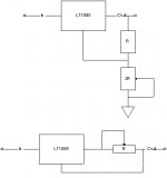
The upper diagram shows the voltage regulator. This is straight from the datasheets (I know I'm missing the caps on both sides for stability), and is fairly easy. The LT1085 will try to have 1.25V across R, so all I need is for the lower resistor to be equal to the upper resistor, and I'll have 2.5V. And if I pick resistors in the 1K range, the currents flowing through them will be in the 1-2mA range, so the 50uA that flows out of the ADJ pin won't upset calculations. Also, 1.25V * 1mA means 1/4W or 1/2W resistors will be fine.
I hope I got that correct?
The lower diagram shows the current regulator, and this is where I have questions. First, is this how I should hook it up? If it is, then for 2.5A, I need a .5 ohm resistor, or more correctly, pot, in order to adjust values accurately. And then I have 2.5^2*.5 = ~3W being dissipated through this, so I'll need a 5-10W 1 ohm pot, which sounds like a slightly unusual component.
Is that correct? Is there a better way of doing this? And finally, starting at the rectifier end, which should come first - the voltage regulator, or the current regulator?
Thanks in advance,
Saurav
Attachments
If you had an ideal component supplier...
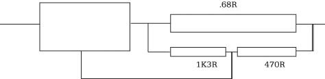
Your current regulator is fine in theory, but as you've realised, not terribly practical. However, that's easily fixed.
Change the 0.5R resistor for a 0.68R 15W metal-clad resistor bolted to your chassis. It will develop 1.7V when 2.5A flows through it. That's too much, so put at potential divider across it to divide it down to 1.25V. A 1k3 resistor from the output of the regulator to a 470R resistor to the far end of the 0.68R sense resistor would do nicely. You now have a 2.5A current regulator. The difference between this and your 0.5R solution is that it's not quite as efficient, but it uses readily available parts. This is the difference between physics and engineering.
If you wanted to be really fussy about setting 2.5A precisely, add a 50R resistor in between the 1k3 and 470R, and take the wiper to the adjust pin of the regulator.
Yer Maun
The bike is a Honda RC45, and it's being piloted by the greatest motorcycle road racer to have ever lived, and a good man, the late Joey Dunlop MBE OBE.
The photo was taken at Signpost Corner on the Isle of Man in 1995 on his way to winning the Senior TT race that year at an average of 119.11mph.
TT course
EC8010 said:Hello Brett. Considering angular acceleration, and its relationship to friction at a rubber/tarmac interface just below the onset of instability; what's the bike in your avatar?
The bike is a Honda RC45, and it's being piloted by the greatest motorcycle road racer to have ever lived, and a good man, the late Joey Dunlop MBE OBE.
The photo was taken at Signpost Corner on the Isle of Man in 1995 on his way to winning the Senior TT race that year at an average of 119.11mph.
TT course

I just woke up, so I had to read your post several times before I could understand it. Just making sure I have it right - is this what you mean? I think I got it right. And yes, this is a much better scheme, and I can adapt that to work with whatever value resistors I find at the surplus store. And I could pick voltage divider resistor values so that they don't pass much current, and I won't need high power parts there.
15W... things are going to get a little tight under the hood
15W... things are going to get a little tight under the hood
Attachments
One more question - will the DC filament supply hook up to the tube any different from the way the AC hooked up? I have a hum pot, and the cathode bias resistor+cap are off the hum pot's wiper. I could leave it that way, and just replace the AC filaments with DC. That would keep the filament 'centered' around ground (or 45V, since it's cathode biased), with one end of the filament being 1.25V above and the other end being 1.25V below. Or I could move the cathode bias resistor to one end of the filament (and get rid of the hum pots), and that would put one end of the filament at 2.5V and the other at 0. Are there any pros/cons to doing it one way or the other?
 ing for a while now with this issue I want to set this up for my new 300bxls SE amp.
Hi,
Yes, it will.
It's much more akin to a IDHT.
As such it doesn't carry the pulsating currents of an AC supply.
With DC on the heater/cathode you don't worry about humbucking, there's no AC present...
Could you use the AC heater tricks to try to heat the cathode evenly? Yes, you can but it will be hard to tell when the cathode is heated evenly...which is why we don't really bother with this.
Most of the time DC finds equilibrium all by itself.
Cheers,
One more question - will the DC filament supply hook up to the tube any different from the way the AC hooked up?
Yes, it will.
It's much more akin to a IDHT.
As such it doesn't carry the pulsating currents of an AC supply.
With DC on the heater/cathode you don't worry about humbucking, there's no AC present...
Could you use the AC heater tricks to try to heat the cathode evenly? Yes, you can but it will be hard to tell when the cathode is heated evenly...which is why we don't really bother with this.
Most of the time DC finds equilibrium all by itself.
Cheers,
- Status
- This old topic is closed. If you want to reopen this topic, contact a moderator using the "Report Post" button.
- Home
- Amplifiers
- Tubes / Valves
- PSUD modelling of a filament supply