Been doing a little experimenting recently and finally got around to putting a 1N5314 in the plate of a miniscule 6DJ8 line amp I have lying around. It's really cramped inside, and has only 120V B+ available, so it made sense to use as small a part as possible. I got Ea = 75V, Ec = 1.6V, Ia = 5mA (of course). The surprise was that it sounds very nice indeed, especially considering its complete lack of anything expensive in the signal path. So that got me to dreaming about changing out all the plate load resistors in my 'real' system for ccs's...
I was reading Walt Jung's AudioXpress articles about ccs. The version with DN2540 or 10M45S on top and an LM317 on the bottom looks to have excellent performance. (I think that's Fig. 13C.)
I've been searching the posts here and I've found this mentioned a couple of times, but only in passing. I haven't seen a real discussion of this particular topic.
I know the ccs using two DN2540's is the favorite, but what if I want a more repeatable, more easily adjusted version? Is putting the LM317 as the bottom half really going to do great damage to the sound of the circuit? It sure doesn't look like the performance suffers.
I have some little perfboards from Radio Shack to wire up. I'm hoping to get a couple of DN2540 + LM317 ccs's wired up this evening, and a couple more with dual DN2540's.
Do you think I'll hear a difference?
--
Wow, ask and you shall receive. One view, one reply! Thanks, SY. I didn't know about the follow-up.
I guess I could use the 317 on the bottom for ease of setup, get things working in-circuit, then swap in the dual-DN2540 version to finish things up. I have a tendency to blow things up if I have to do too much tweaking, and I only have a few DN2540's.
I guess I could use the 317 on the bottom for ease of setup, get things working in-circuit, then swap in the dual-DN2540 version to finish things up. I have a tendency to blow things up if I have to do too much tweaking, and I only have a few DN2540's.
I have found that the DN2450s are remarkably consistent, at least within a given batch. However, if you don't use a stopper resistor while you're sorting, the results will wander all over the place due to oscillation. I had to retrofit my fet sorting jig with 1k stoppers, as I was getting wandering results even with medium-gm devices like the J110. My sorting jig uses variable current sources so I can select for Vgs for a given drain current.
So that got me to dreaming about changing out all the plate load resistors in my 'real' system for ccs's...
I know the ccs using two DN2540's is the favorite, but what if I want a more repeatable, more easily adjusted version?
Consider a gyrator instead of a CCS - a couple extra resistors and a small cap. Adjust with a divider at the power supply. Also, the DN2540 is really useful, because it's a high voltage part. But the lower device doesn't have to be. Nor does it have to be depletion mode for the gyrator. You can use a low voltage JFet or MosFet in a TO92 package.
Sheldon
Bump.
Has anyone successfully built this circuit?
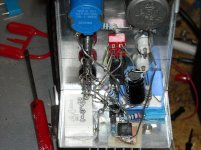
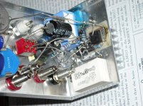
I've tried this circuit three times and keep blowing the DN2540 and LM317.
Yes, I have a G-S protection diode.
I also installed three reverse biased protection diodes to protect against reverse voltage during power down.
First pix is with GS diode, before adding 1N4007s. Second pix is with the 1N4007s added.
Has anyone successfully built this circuit?
I've tried this circuit three times and keep blowing the DN2540 and LM317.
Yes, I have a G-S protection diode.
I also installed three reverse biased protection diodes to protect against reverse voltage during power down.
First pix is with GS diode, before adding 1N4007s. Second pix is with the 1N4007s added.
Attachments
LM317 can work well as output stage constant current sinks where the bypass cap dominates the sound. Other than that there are cheap and easy alternatives.
I am currently using TL783 125V versions of the LM317 which are much more rugged in power up and down situations. I also protect with 100V zeners.
Shoog
I am currently using TL783 125V versions of the LM317 which are much more rugged in power up and down situations. I also protect with 100V zeners.
Shoog
I used a small price of single sided PCB. I trimmed back the copper for a 0.1" border and soldered the part to it. It acts as an insulator to prevent the LM317 from touching the chassis. I also put silicon grease on the back of the board and it is in good contact with the case.
LM317 can work well as output stage constant current sinks where the bypass cap dominates the sound. Other than that there are cheap and easy alternatives.
I am currently using TL783 125V versions of the LM317 which are much more rugged in power up and down situations. I also protect with 100V zeners.
Shoog
Hi Shoog,
Any suggestions on protecting the LM317 during power-up/power-down?
I used a small price of single sided PCB. I trimmed back the copper for a 0.1" border and soldered the part to it. It acts as an insulator to prevent the LM317 from touching the chassis. I also put silicon grease on the back of the board and it is in good contact with the case.
The 317 is probably cooking, PC board isn't very good at wicking heat away to the chassis.
May be it's the cathode voltage rise on power up, before filaments have heated enough to draw current and bring the voltage back down again?
Just a thought.
- Status
- This old topic is closed. If you want to reopen this topic, contact a moderator using the "Report Post" button.
- Home
- Amplifiers
- Tubes / Valves
- DN2540 + LM317 cascode CCS?