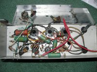
I can't find a can type capacitor with 40uf 20uf 10uf and 4uf. I know there are a lot smarter people on here than myself so I ask some assistance on outfitting this thing with new caps. I tested all the tubes and there are plenty of life in them (telefunken EF86, Bugle Boy made in holland 12AU7, RCA 6AX5, RCA 6V6GT's)
http://recordist.com/ampex/schematics/612man/ampex612.jpg
above is link to schematic
http://recordist.com/ampex/schematics/612man/ampex612.jpg
above is link to schematic
Attachments
Last edited:
Those are simply filter caps coming off the PS - so no big deal (please don't start a debate) in terms of affecting the audio. As DF96 suggested I'd just use some suitable subs. Outside of that check on some of the HAM radio sites - those guys can scrounge up almost anything. The problem is the parts are often old and hard to put full faith in. YMMV
Assuming the 40uF and 20uF are for the PSU, you may be able to buy a 40+40 or 50+50 can which will fit. Then use separate ones for the others. They will be light enough to be supported by their own wires so just solder in to an existing tag if possible. If not add a small tag strip somewhere.
NOS caps will need to be reformed - Google for details. This process applies a small current to rebuild the oxide layer.
NOS caps will need to be reformed - Google for details. This process applies a small current to rebuild the oxide layer.
I can't find a can type capacitor with 40uf 20uf 10uf and 4uf. I know there are a lot smarter people on here than myself so I ask some assistance on outfitting this thing with new caps...
Get a three or two section can cap. With sections at least as large. It is easy to find a 40, 40 or a 40, 40, 20. Then get an axial 4uF cap and wire that in point to point.
It's worth upgrading the size of the filter caps EXCEPT do not make the first one larger than 40uF. I would not even go to 47uF without first checking the data sheet for the rectifier tube. Most tubes have a spec for the largest allowable filter cap. But after that first one going up to a larger size does no harm and likely some good so don't spend a lot of time looking for an exact match.
JJ Can Capacitor 40µF x 20µF x 20µF x 20µF / 500V
So I could use something like this and just not use the last 20uf section? Can I use a 8uf instead of a 4uf?
So I could use something like this and just not use the last 20uf section? Can I use a 8uf instead of a 4uf?
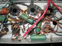
Imho, add 3-4 small tag strips around the chassis and take all signal earths to them using a distributed star distribution with single point chassis connection. Use two tag strips soldered to the existing electro, such that new individual electro's are soldered between the new tags. This keeps the same aesthetic look above the chassis. New electro's are much much better than old NOS, and so much smaller. You've got ton's of room.
Ciao, Tim
Ciao, Tim
JJ Can Capacitor 40µF x 20µF x 20µF x 20µF / 500V
So I could use something like this and just not use the last 20uf section? Can I use a 8uf instead of a 4uf?
You can use the last section. 20uF is a more reasonable value anyways. You have to remember that these old amps were built to a cost
The advice above to not even use a can cap is good. Can caps are grounded to the chassis. Better to use a star ground. But the JJ cap look to be a drop in upgrade
Last edited:
Imho, add 3-4 small tag strips around the chassis and take all signal earths to them using a distributed star distribution with single point chassis connection. Use two tag strips soldered to the existing electro, such that new individual electro's are soldered between the new tags. This keeps the same aesthetic look above the chassis. New electro's are much much better than old NOS, and so much smaller. You've got ton's of room.
Ciao, Tim
This is good advice. Modern electrolytics on tagstrip is easy and cheap, and sounds better than multiple section types. The multi-sections often have ripple-current ratings of only 200 .. 300mA, which is not enough for larger amps, and short life results.
I recommend the Panasonic TSUP or TSHA or Nichicon KX, and the Nichicon VR for smaller sizes, as 'known good' sounding.
If you care about the sound quality, please buy brand new caps from Farnell, Mouser etc. Electrolytics degrade quite quickly in storage AND use - they are electrochemical liquid soaked in a bit of hemp, stuck in a can with a rubber stopper. Used caps, ebay sales, "NOS" purchases, Rally/Hamfest, nonfranchised distis and the like are a bad choice. They seem to measure OK when they are 10 years old, for C and ESR (I use a proprietory ESR meter, but the difference is easily distinguishable by listening.
The cheapest, most versatile and easiest solution is to leave the old can in place, but disconnect it, and add separate caps for each of the values of the original can, using a tag strip or simply mount them onto the existing circuitry. I'd leave the original can in place for aesthetic purposes.
If you use the old can as a tie point without removing the contents, it can still short and explode. Forget Mastodon's advice, cleaning up after a cap explosion is not worth it. "tag board" is my preferred solution, but they are not called that here. They are called "terminal strips", ie the brown phenolic strips of contacts mounted on a bracket for screws. The only places in the US I have found to buy terminal strips is tubesandmore.com in AZ, and electronicsurplus.com in NY. I mount them on 6-32 screws with elastic stop nuts. If you have to drill holes, use a magnet near the bit, and a hand crank drill throws less metal trash around. I tend to remove the can, and put metal mesh over the opening for air vents, tied down with twisted wire. I've done 2 1/2 hammond organs, the ST70 amp, and the PAS2 preamp lately, although I used a stock can cap on the preamp.
You could also use a 40-20-10-10 stock cap if you put a little extra resistance between the rectifier and the first cap. 47 ohm @ 3 W seems to be useful, although for 5AR4's you need 5W resistors, I have proved by experiment. 47 ohm chokes are even cooler than resistors.
You could also use a 40-20-10-10 stock cap if you put a little extra resistance between the rectifier and the first cap. 47 ohm @ 3 W seems to be useful, although for 5AR4's you need 5W resistors, I have proved by experiment. 47 ohm chokes are even cooler than resistors.
Last edited:
http://www.mouser.com/catalog/catalogUSD/643/1618.pdf
Mouser carries the classic terminal strips. A decent but not perfect copy of the old ones.
Mouser carries the classic terminal strips. A decent but not perfect copy of the old ones.
Yup, I figured he meant terminal strips. Not sure if I will redistribute the grounds, I know it is a good idea. If I did I would probably seperate the preamp stage from the output stage grounds. Power supply grounds (PT center tap, first filter cap ground) and output stage grounds (output tube cathodes for fixed bias, or cathode resistors for cathode biased, and output transformer secondary ground) are connected together and to the chassis at a single point, right at the ground of the first filter capacitor. The ground of the second filter capacitor, after the choke or filter resistor, is the star ground point for the preamp stage grounds. Use a local common point for each preamp stage ground, and run a wire from this common point back to the second star point.
Yup, I figured he meant terminal strips. Not sure if I will redistribute the grounds, I know it is a good idea. If I did I would probably seperate the preamp stage from the output stage grounds. Power supply grounds (PT center tap, first filter cap ground) and output stage grounds (output tube cathodes for fixed bias, or cathode resistors for cathode biased, and output transformer secondary ground) are connected together and to the chassis at a single point, right at the ground of the first filter capacitor. The ground of the second filter capacitor, after the choke or filter resistor, is the star ground point for the preamp stage grounds. Use a local common point for each preamp stage ground, and run a wire from this common point back to the second star point.
I would not change the grounding scheme. There are probably more ground points than are obvious and that can lead to big surprises.
I would not change the grounding scheme. There are probably more ground points than are obvious and that can lead to big surprises.
Yup, going to buy some terminal strips and axial caps and call it a day

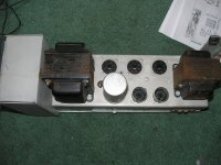
Terminal strips (as per what is in the amp now) can be soldered in place - eg. to the existings cap terminals when it is disconnected, or to chassis ground connection tabs. You only need to use a small 'two' terminal strip (the mounting terminal is soldered to the chassis and not used for any other purpose) for distributed ground function. Looks like there are five chassis ground points. A separate mains protective earth would need to be added, as well as a fuse. A humdinger pot may also be usefull to trim hum to negligible level (whether taken to 0V, or to bypassed cathode of output stage).
Ciao, Tim
Ciao, Tim
Looks like your can is not soldered directly to the chassis which makes removal much easier than otherwise. Often some/all of the "tabs" that touch the chassis will be soldered to it. In this case I would get a C-EC40-20-20 from
Antique Electronic Supply and use a 20 on the new can for the "10" position and a loose one for the "4" position.
I think the spacing of the mounting tabs is standard but checking that dimension is a good idea.
Antique Electronic Supply and use a 20 on the new can for the "10" position and a loose one for the "4" position.
An externally hosted image should be here but it was not working when we last tested it.
I think the spacing of the mounting tabs is standard but checking that dimension is a good idea.
- Status
- This old topic is closed. If you want to reopen this topic, contact a moderator using the "Report Post" button.
- Home
- Amplifiers
- Tubes / Valves
- Recapping old tube amp