not sure if you missed it in various buck converter application notes, but a second inductor+capacitor stage will reduce ripple, you can also try using a slightly larger inductance
go for the usual 10% rule of thumb for filter+inductor
i too am designing a buck converter, havent purchased any parts yet, however. Myself, im designing a 100mA to 5~8 amp 5~24v range regulator for powering various equipment unrelated to tubes with my friend... but i suppose it could be used for them too, huh
using microcontroller for feedback/real time control (going to be operating about 8 buck converters, plus monitoring thermocouples and voltages)
my specs so far are 220 uH and 10 uH with 470/47 uF capacitors, intend to use IRF3205 mosfets, waaay overkill but they are cheap and are very fast switching/easy to drive. havent decided yet on the diode
Last edited:
Tom, The convenience is unbeatable, and for IDHTs it will be a winner. For
Directly Heated Triodes, though, the sonic performance will be some way short of
what is possible, for a number of reasons:
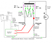
- Anode [plate] current in the filament: looking at the sketch attached, the
anode current flows in the filament substrate [ie the wire] to supply the
emission sites all along the length of the filament.
In a 300B DHT, running the standard 60mA, the portion of the filament nearest
FIL+ will carry the whole 60mA, with lower fractions of current found as you
work back toward FIL-.
Keeping Kirchoff in mind, the anode current and the Filament current flow
together indistinguishably in the filament wire. SO - Any disturbance in the
filament current supply will directly reflect as a disturbance in the anode
current - and remember, the 300B output is the anode current - it's not a
voltage!
This is a real risk to the quality of the 300B stage. Consider this: the little
10mV spikes on the switcher's output seem innocent enough - but what happens to
the current? Well the 300B filament is 5V 1.3A = 3.8 ohms [hot]. 10mV peaks give
2.7mA peaks of current in the filament.....which is imposed directly on the
anode current [since this is much higher impedance circuit than the filament
supply's]. This amounts to a 4.5% distortion current on 60mA. Of course, this is
mostly ultrasonic energy, but not entirely, since the duty-ratio of a
buck-converter bounces up & down with the input voltage, which in this case will
be the raw dc ripple and mains noise. This effect will produce large amounts of
spectrum at audio frequencies.
This current-mixing effect is the reason why simple Bridge + Cap dc heated DHTs
sound worse than any other heating method. In this case, the filament current is
modulated by many mA of ripple current, plus the rectifier recovery **current**
pulses, which start life at the 1.3A level equal to the dc current.
With ac heating, the effect of 50/60Hz current is cancelled by means of an
unbalanced pot, which equalises the 50/60Hz current in each half of the
filament. More accurately, it nearly cancels the current, since there is
second-harmonic distortion of the filament current, which does **not cancel** as
proved by Dmitry Nizhegorodov:
On Correlation Between Residual DHT Filament Hum and AC Frequency. Distortion-induced hum in directly-heated triodes.
ac heat also forces the anode current to be shunted around the transformer
secondary winding, where it is exposed to magnetic and electrostatic noise, and
bad dielectrics.
Other problems to be tackled:
With a switcher the output cap may be 100uF or so, which may present 50 ohms or
so at bass frequencies. This is shunting the filament, whose impedance is about
4 ohms at all audio frequecies, as above. Now we have the anode current taking a
frequency-selective diversion around the output cap, opening the risk of
colourations, both from the frequency-selective shunting, and from forcing
some of the anode current through electrolytic and high-K ceramic switcher-caps!
This is one of the reasons that a high-dynamic-impedance CCS improves DHT
heating, since the anode current remains contained within the cathode circuit,
and does not get diverted around the filament heating circuit.
The other reason CCS drive sounds so good is because the feedback for the
heating current does not sense at the filament terminals. This is important,
since the filament terminals do not distinguish between the anode-current
signal and the filament current, and you wind up mixing the anode current into
the closed loop of the heating current. CCS heating senses the filament supply
current ONLY, at the supply input, and does not sense or influence the anode
current in any way. This advantage cannot be had by any circuit which senses the
filament voltage.
CCS heating with 3-terminal regulator ICs also falls short - partly because
their input terminals do not adequately reject anode signals at the input, and
partly due to their excessive voltage noise, which translates into current
noise in the anode current.
folks who have tried my filament heater [from the last pages of the New DHT
Heater thread] often remark on the improvement over 317 or LT108x CCS heating.
Directly Heated Triodes, though, the sonic performance will be some way short of
what is possible, for a number of reasons:
- Anode [plate] current in the filament: looking at the sketch attached, the
anode current flows in the filament substrate [ie the wire] to supply the
emission sites all along the length of the filament.
In a 300B DHT, running the standard 60mA, the portion of the filament nearest
FIL+ will carry the whole 60mA, with lower fractions of current found as you
work back toward FIL-.
Keeping Kirchoff in mind, the anode current and the Filament current flow
together indistinguishably in the filament wire. SO - Any disturbance in the
filament current supply will directly reflect as a disturbance in the anode
current - and remember, the 300B output is the anode current - it's not a
voltage!
This is a real risk to the quality of the 300B stage. Consider this: the little
10mV spikes on the switcher's output seem innocent enough - but what happens to
the current? Well the 300B filament is 5V 1.3A = 3.8 ohms [hot]. 10mV peaks give
2.7mA peaks of current in the filament.....which is imposed directly on the
anode current [since this is much higher impedance circuit than the filament
supply's]. This amounts to a 4.5% distortion current on 60mA. Of course, this is
mostly ultrasonic energy, but not entirely, since the duty-ratio of a
buck-converter bounces up & down with the input voltage, which in this case will
be the raw dc ripple and mains noise. This effect will produce large amounts of
spectrum at audio frequencies.
This current-mixing effect is the reason why simple Bridge + Cap dc heated DHTs
sound worse than any other heating method. In this case, the filament current is
modulated by many mA of ripple current, plus the rectifier recovery **current**
pulses, which start life at the 1.3A level equal to the dc current.
With ac heating, the effect of 50/60Hz current is cancelled by means of an
unbalanced pot, which equalises the 50/60Hz current in each half of the
filament. More accurately, it nearly cancels the current, since there is
second-harmonic distortion of the filament current, which does **not cancel** as
proved by Dmitry Nizhegorodov:
On Correlation Between Residual DHT Filament Hum and AC Frequency. Distortion-induced hum in directly-heated triodes.
ac heat also forces the anode current to be shunted around the transformer
secondary winding, where it is exposed to magnetic and electrostatic noise, and
bad dielectrics.
Other problems to be tackled:
With a switcher the output cap may be 100uF or so, which may present 50 ohms or
so at bass frequencies. This is shunting the filament, whose impedance is about
4 ohms at all audio frequecies, as above. Now we have the anode current taking a
frequency-selective diversion around the output cap, opening the risk of
colourations, both from the frequency-selective shunting, and from forcing
some of the anode current through electrolytic and high-K ceramic switcher-caps!
This is one of the reasons that a high-dynamic-impedance CCS improves DHT
heating, since the anode current remains contained within the cathode circuit,
and does not get diverted around the filament heating circuit.
The other reason CCS drive sounds so good is because the feedback for the
heating current does not sense at the filament terminals. This is important,
since the filament terminals do not distinguish between the anode-current
signal and the filament current, and you wind up mixing the anode current into
the closed loop of the heating current. CCS heating senses the filament supply
current ONLY, at the supply input, and does not sense or influence the anode
current in any way. This advantage cannot be had by any circuit which senses the
filament voltage.
CCS heating with 3-terminal regulator ICs also falls short - partly because
their input terminals do not adequately reject anode signals at the input, and
partly due to their excessive voltage noise, which translates into current
noise in the anode current.
folks who have tried my filament heater [from the last pages of the New DHT
Heater thread] often remark on the improvement over 317 or LT108x CCS heating.
Attachments
ryuji, sometimes 'waaay overkill' in certain device parameters in smps can lead to poorer performance in other aspects. Eg. lowering Rds-on with fets typically leads to higher switching loss and emi. Balancing parameters is always a compromise.
You have a good point, I was thinking they would be good for the purpose as I need them for other projects, might be worth getting more exact components
not sure if you missed it in various buck converter application notes, but a second inductor+capacitor stage will reduce ripple, you can also try using a slightly larger inductance
go for the usual 10% rule of thumb for filter+inductor
As you can see from the oscilloscope shot I'm measuring 2~3 mVpp of ripple. It's hard to tell the magnitude exactly as it's approaching the measurement limit of the scope (Tek 2465B, P6139 probe). I'm really not concerned with it. Also, note that it's way out of the audio band.
For a filament heater, the 2~3 mV ripple will get smoothed out nicely by the thermal time constant of the filament. The question that remains is if it will couple to sensitive nodes in the circuit. I kinda doubt it - 800 kHz is not that high frequency and the coupling capacitances are in the pF range. It also hasn't been an issue in switching filament regulators I've built in the past. But, of course, it needs to be verified.
~Tom
This is a real risk to the quality of the 300B stage. Consider this: the little
10mV spikes on the switcher's output seem innocent enough - but what happens to
the current? Well the 300B filament is 5V 1.3A = 3.8 ohms [hot]. 10mV peaks give
2.7mA peaks of current in the filament.....which is imposed directly on the
anode current [since this is much higher impedance circuit than the filament
supply's]. This amounts to a 4.5% distortion current on 60mA. Of course, this is
mostly ultrasonic energy, but not entirely, since the duty-ratio of a
buck-converter bounces up & down with the input voltage, which in this case will
be the raw dc ripple and mains noise. This effect will produce large amounts of
spectrum at audio frequencies.
Its happening at 800Khz, far higher than ultrasonic. That will be smoothed out because the heating time of the filament is not instant. It can only be modulated so fast.
Your AC line is not as clean as you think. Any low frequency garbage on it will go right through a transformer.
Naturally, the heating time-constant will suppress effects due to heating variation. But that is not the problem at all - it's the fact the filament current and the anode current are flowing in the same conductor, and that any noise, ripple or disturbance in the filament current will appear in the amplifier's output by simple conduction.
The switching may happen at 800kHz, but that's just the "carrier". A buck converter is just like a class D PWM amplifier, where the PWM duty is varying with the ripple and noise on the incoming raw dc. This certainly has audio frequency components, and this is what pollutes the DHT stage.
I agree, AC line is a terrible source of noise - my solution uses low capacitance [high insertion loss] buffering on **both** sides of the filament.
Dear Rod,
I have absolutely no desire to turn this thread into a religious flame war about constant current vs constant voltage. But I do feel the need to at least address some of your concerns.
I have tried linear regulators (LM317 and the like) both for constant voltage and constant current. I also tried a lab supply that can be switched between constant current and constant voltage. I could not tell any difference between constant current or constant voltage neither in measurements nor in listening tests. The testing was done on my 300B amp (directly heated triode). I have also compared LM317, constant voltage to a switching regulator (LMZ12002). I could not tell any difference in sound between the different types of regulators. However, I did note that the switcher didn't result in any ill effects, the amp still measured and sounded well.
Even though the individual components of a switching regulator are more expensive than an LM317 and a few resistors, the switcher still wins on cost when the cost of the heatsink needed for the LM317 is considered. So same sound quality, lower cost, less heat to get rid of... The switcher sounds like a clear winner to me.
You are making the assumption that one electron in the space-charge cloud is distinguishable from another. That argument is false. I'm sorry... Physics just don't work that way.
If the switching spikes really caused 4.5 % distortion, I'm sure I would be able to pick it up with my HP 8903A distortion analyzer. It's noise/distortion floor is 0.002 % THD+N.
A well designed regulator (like any modern switching regulator) is designed to be as immune to variations in the input voltage as possible. This is characterized in a figure called line regulation. What you are describing above sounds like an unstable system. A well designed regulator is a stable system. A well designed regulator will provide a constant output voltage for any variation in load or input voltage (within limits, of course).
In any event, should this regulator turn into a happy bounce house with duty cycles varying all over the map and causing nasty, nasty audio frequency intermodulation products, I'm absolutely certain that it will be picked up by my HP 3562A dynamic signal analyzer. Its -145 dBV noise floor can hear the grass grow, trust me. In previous experiments, no switching-induced IM products were found. In fact the 120 Hz, and 240 Hz components were reduced by almost 20 dB by the switching supply due to its better line regulation.
Except for the "current-mixing effect" which I believe is bogus as outlined above, I am willing to buy that statement. Double-rectified and smoothed DC is a rather nasty waveform with a lot of harmonic content. Also, in applications where significant current is drawn, the ripple voltage becomes harder to keep within reasonable limits. Hence, the amplitude of the nasty harmonic content becomes sizable and will couple into the circuit. This forms various IM products that can easily be picked up by a spectrum analyzer (such as the 3562A I mentioned before).
Between the cathode/filament and grid is a coupling capacitor. This capacitor is not a real capacitor (i.e. physical component) but rather a parasitic capacitor. Unfortunately, the way physics work is that when you have two conductors in proximity of one another they form a capacitor whether you want it or not. So any AC voltage present on the cathode will couple to the grid (and anode). It doesn't matter if this voltage is the 2~3 mVpp @ 800 kHz that comes out of my regulator, or the ripple/noise that's present on the output of a constant current source regulator, or the AC from a filament winding on a transformer. But in case of the filament winding, the voltage on one end of the coupling cap is 6.3 VAC. That's a sizable voltage. By using a humdinger pot, this voltage is reduced to 3.15 VAC. That's how a humdinger works. It has nothing to do with electron emission. It's simple capacitive coupling.
No it doesn't. Poor circuit design forces the anode current to return to the mains. In a well-designed circuit, the AC signal path for the anode current consists of the OPT, the output tube, and a high-quality cap from the cathode to the B+ end of the OPT primary. See Loftin-White for more information. This trick has been employed in modern measurement gear as well, by the way.
I did read through the rest of your response - including the website you linked to. I considered picking the arguments apart one by one, but as I said to begin with, I don't want this thread to turn into a flame war.
My fundamental point is this: A well-engineered, well-designed circuit will have superior performance over one that is not well-engineered or well-designed. I intend to design a filament regulator that performs well both when considered as a stand-alone voltage source and when used for a filament supply in either a directly headed triode or an indirectly heated tube. I will back up my claims with measurements and I will base my design decisions on facts and measured data. To me - as an engineer and a scientist - that's a reasonable approach. Others are free to disagree.
~Tom
I have absolutely no desire to turn this thread into a religious flame war about constant current vs constant voltage. But I do feel the need to at least address some of your concerns.
I have tried linear regulators (LM317 and the like) both for constant voltage and constant current. I also tried a lab supply that can be switched between constant current and constant voltage. I could not tell any difference between constant current or constant voltage neither in measurements nor in listening tests. The testing was done on my 300B amp (directly heated triode). I have also compared LM317, constant voltage to a switching regulator (LMZ12002). I could not tell any difference in sound between the different types of regulators. However, I did note that the switcher didn't result in any ill effects, the amp still measured and sounded well.
Even though the individual components of a switching regulator are more expensive than an LM317 and a few resistors, the switcher still wins on cost when the cost of the heatsink needed for the LM317 is considered. So same sound quality, lower cost, less heat to get rid of... The switcher sounds like a clear winner to me.
- Anode [plate] current in the filament: looking at the sketch attached, the anode current flows in the filament substrate [ie the wire] to supply the emission sites all along the length of the filament.
In a 300B DHT, running the standard 60mA, the portion of the filament nearest FIL+ will carry the whole 60mA, with lower fractions of current found as you work back toward FIL-.
You are making the assumption that one electron in the space-charge cloud is distinguishable from another. That argument is false. I'm sorry... Physics just don't work that way.
This is a real risk to the quality of the 300B stage. Consider this: the little 10mV spikes on the switcher's output seem innocent enough - but what happens to the current? Well the 300B filament is 5V 1.3A = 3.8 ohms [hot]. 10mV peaks give 2.7mA peaks of current in the filament.....which is imposed directly on the anode current [since this is much higher impedance circuit than the filament supply's]. This amounts to a 4.5% distortion current on 60mA.
If the switching spikes really caused 4.5 % distortion, I'm sure I would be able to pick it up with my HP 8903A distortion analyzer. It's noise/distortion floor is 0.002 % THD+N.
Of course, this is mostly ultrasonic energy, but not entirely, since the duty-ratio of a buck-converter bounces up & down with the input voltage, which in this case will be the raw dc ripple and mains noise. This effect will produce large amounts of spectrum at audio frequencies.
A well designed regulator (like any modern switching regulator) is designed to be as immune to variations in the input voltage as possible. This is characterized in a figure called line regulation. What you are describing above sounds like an unstable system. A well designed regulator is a stable system. A well designed regulator will provide a constant output voltage for any variation in load or input voltage (within limits, of course).
In any event, should this regulator turn into a happy bounce house with duty cycles varying all over the map and causing nasty, nasty audio frequency intermodulation products, I'm absolutely certain that it will be picked up by my HP 3562A dynamic signal analyzer. Its -145 dBV noise floor can hear the grass grow, trust me. In previous experiments, no switching-induced IM products were found. In fact the 120 Hz, and 240 Hz components were reduced by almost 20 dB by the switching supply due to its better line regulation.
This current-mixing effect is the reason why simple Bridge + Cap dc heated DHTs sound worse than any other heating method.
Except for the "current-mixing effect" which I believe is bogus as outlined above, I am willing to buy that statement. Double-rectified and smoothed DC is a rather nasty waveform with a lot of harmonic content. Also, in applications where significant current is drawn, the ripple voltage becomes harder to keep within reasonable limits. Hence, the amplitude of the nasty harmonic content becomes sizable and will couple into the circuit. This forms various IM products that can easily be picked up by a spectrum analyzer (such as the 3562A I mentioned before).
With ac heating, the effect of 50/60Hz current is cancelled by means of an unbalanced pot, which equalises the 50/60Hz current in each half of the filament.
Between the cathode/filament and grid is a coupling capacitor. This capacitor is not a real capacitor (i.e. physical component) but rather a parasitic capacitor. Unfortunately, the way physics work is that when you have two conductors in proximity of one another they form a capacitor whether you want it or not. So any AC voltage present on the cathode will couple to the grid (and anode). It doesn't matter if this voltage is the 2~3 mVpp @ 800 kHz that comes out of my regulator, or the ripple/noise that's present on the output of a constant current source regulator, or the AC from a filament winding on a transformer. But in case of the filament winding, the voltage on one end of the coupling cap is 6.3 VAC. That's a sizable voltage. By using a humdinger pot, this voltage is reduced to 3.15 VAC. That's how a humdinger works. It has nothing to do with electron emission. It's simple capacitive coupling.
ac heat also forces the anode current to be shunted around the transformer secondary winding, where it is exposed to magnetic and electrostatic noise, and bad dielectrics.
No it doesn't. Poor circuit design forces the anode current to return to the mains. In a well-designed circuit, the AC signal path for the anode current consists of the OPT, the output tube, and a high-quality cap from the cathode to the B+ end of the OPT primary. See Loftin-White for more information. This trick has been employed in modern measurement gear as well, by the way.
I did read through the rest of your response - including the website you linked to. I considered picking the arguments apart one by one, but as I said to begin with, I don't want this thread to turn into a flame war.
My fundamental point is this: A well-engineered, well-designed circuit will have superior performance over one that is not well-engineered or well-designed. I intend to design a filament regulator that performs well both when considered as a stand-alone voltage source and when used for a filament supply in either a directly headed triode or an indirectly heated tube. I will back up my claims with measurements and I will base my design decisions on facts and measured data. To me - as an engineer and a scientist - that's a reasonable approach. Others are free to disagree.
~Tom
The switching may happen at 800kHz, but that's just the "carrier". A buck converter is just like a class D PWM amplifier, where the PWM duty is varying with the ripple and noise on the incoming raw dc. This certainly has audio frequency components, and this is what pollutes the DHT stage.
The whole purpose of having a regulator in the first place is to make the output of the regulator independent of the input. Any voltage regulator (be it switching or linear) compares the OUTPUT voltage to an internal reference voltage. The reference voltage is designed to be independent of the input voltage, temperature variations, etc. In silicon devices, a temperature compensated bandgap circuit is typically used. In discrete circuits, a zener or silicon bandgap IC may be used. In tube circuits, the predictable breakdown voltage of a neon (or other noble gas) bulb has been used. The line regulation (how efficient the regulator is at separating the output voltage from the input voltage) is generally dictated by how much the reference voltage varies with the input voltage. This is completely independent on the regulator topology used.
~Tom
Tom, it looks like you have to solder the pad on the bottom of that thing as well. Is that pretty easy to do?
You are correct. The DAP is exposed and is the dominant path for heat transfer. It will need to be soldered to the board. For the final boards, I will have a matrix of vias connecting the pad for the DAP with the ground plane on the bottom of the board (as well as the top plane) and likely use 75 um copper (2 oz) for better heat transfer.
For the smaller packages where you can see the pins, I generally find that they are pretty easy to hand solder -- especially on a board with solder mask. That goes for this bugger as well. I use a regular ol' heat gun. A good preheat of 15~20 seconds on the low setting, followed by whatever it takes on the high setting to get the solder to melt. It usually takes another 10~15 seconds. Then I make sure the part is centered and move the board away from the heat gun and allow it to cool.
I use regular 60/40 lead solder with rosin flux core. I pre-tin the pad before placing the part and heating the board with the heat gun. I also use plenty of flux. A Kester brand flux pen is $5 at Digikey.
The trick is to use flux and to be careful with the heat gun so the board doesn't get burnt. But it's not rocket surgery...
I suppose with the thermal vias connecting top and bottom layer, one could also use a wide chisel tip on a regular soldering iron. That would provide more control over the temperature. I'll definitely try that once I have boards made for this. I have left an opening in the bottom solder mask for this exact purpose.
With 5 V out @ 2.5 A, the LM3102 gets pretty hot. Last night I was measuring the temperature on the outside of the case to be 70~80 deg C. But I was also running a bit high on the switching frequency and my prototype board has no thermal vias.
~Tom
Tom, I am surprised to hear you found my comments in any way religious or
provocative of flames. That is not my intention at all, I assure you.
I regard this forum as a place for serious discussion and analysis of
technical matters, and would like to be able to offer criticism so as to provoke
discussion, not disputes. The account I gave above is mostly composed of
technical analysis, illustrated and quantified where possible.
Many contributors here know that I have been engaged in researching
Direct-Heated Triode filament supplies, and reporting here, for the best part of
a decade. Under such circumstances, I can hardly hold back from entering a
discussions on the subject, can I?
So, let's have an entirely non-religious debate on the subject! I promise not to
say anything even remotely smelling of flame. However, I don't promise to avoid
mentioning my listening impressions, and the listening impressions of others on
this forum, since the purpose of building our own audio is to give pleasure, by
way of music. Many people here (literally hundreds) have tried out my ideas, and
heating solutions that I offer, and expressed surprise at how much improvement
they make. I'll admit that my solution is not as convenient as a switcher, but
my goal is all-out sonic performance, at modest cost.
To begin: I think the big difference between us is this:
I say: That the filament heating current flows in a filament wire in a DHT. The
same wire is terminated for connexion to the heating supply. The same wire
is also coated with emissive [cathode] material, and emits electrons towards the
anode [plate], which form the anode current. One [or both] of the same
filament terminals is connected to the anode supply's return path.
Therefore, filament current and anode current flow in the same conductor.
Therefore noise and disturbance in the one current are added to the current of
the other. We can ignore the question of distribution across the length of the
filament [for now] - since even if the anode current flows across a tiny
portion of the filament wire, it will still MIX with the filament
current.... it has to because the filament current must flow through every
part of the filament wire, by definition. The diagram I posted [#23] illustrates
what I say here.
For there to be no current mixing, the filament heating current would need to
flow on a different conductor to the "cathode" of the tube..... but then we
would not have a DIRECTLY heated triode.
This is the great difficulty with DHTs! Because of current-mixing, they respond
to minute attention and care to the heating circuit, because the errors
in the heating circuit are imposed upon the the anode current.
We may have built a wonderful regulator for 5V 1.3A supply, and measure
artefacts in the voltage output to be 0.1%. Ok, so 5mV in 5V, great.
But, connect a 4 ohm load [=300B filament] and you get artefacts of 1.3mA,
imposed on a 60mA signal current - > 2%, of full output signal. That's the
reason dc-unregulated [and some regulated] filaments still hum!
With listening tests, this effect is obvious. To me and many others... so if
you don't measure it, well, come on - let's dig into the analysis and find out
where the energy is going. I am genuinely and openly interested to explore it.
Last edited:
Rod,
I didn't find your comments provocative or inflammatory. But I'm not really interested in turning this into a discussion about constant current vs constant voltage.
Your entire hypothesis hinges on this mythical current mixing effect, that is unsupported by physics for reasons I explained in a previous post. That makes it rather uninteresting to me.
If you claim other regulators cause hum but yours doesn't; show me the data. Show before/after graphs of the noise/hum/emi from your amp. Back you claims up with data.
~Tom
Tom, the aim of my post was to offer a critical analysis of the switcher solution. I used the data you displayed, and calculated some likely effects.
The current mixing effect is supported perfectly by Physics - it's simply Kirchoff's Current Law: We have two currents entering/emerging from one conductor, therefore Kirchoff Rules, No exceptions.
But, if you won't entertain my criticism, fine. I leave it for others to make of it what they will.
The current mixing effect is supported perfectly by Physics - it's simply Kirchoff's Current Law: We have two currents entering/emerging from one conductor, therefore Kirchoff Rules, No exceptions.
But, if you won't entertain my criticism, fine. I leave it for others to make of it what they will.
Interesting,
So if we have a current from two different sources one smooth the other with hash on it added togeather at a common point the one will not modulate the other? (similar to mains supply with RFI riding on the top of it). If we split the mains supply we don't get a clean and dirty signal we have a current split equal to the two added togeather. (with hash on both)?
Regards
M. Gregg
We may have built a wonderful regulator for 5V 1.3A supply, and measure
artefacts in the voltage output to be 0.1%. Ok, so 5mV in 5V, great.
But, connect a 4 ohm load [=300B filament] and you get artefacts of 1.3mA,
imposed on a 60mA signal current - > 2%, of full output signal. That's the
reason dc-unregulated [and some regulated] filaments still hum!
With listening tests, this effect is obvious. To me and many others... so if
you don't measure it, well, come on - let's dig into the analysis and find out
where the energy is going. I am genuinely and openly interested to explore it.
If your theory is correct then it should be measurable.
Emission from filaments is not instantaneous, there is a delay from cold to operating temperature. What that delay is I don't know. I do know that it occurs a lot slower than the time between those 800Khz spikes, which should easily filter easily with a ferrite choke. If the filament behaved with the speed of an LED then I could believe you.
Analyze these ideas on paper all you want to. Eventually it comes down to real world measurements.
Emission from filaments is not instantaneous, there is a delay from cold to operating temperature. What that delay is I don't know. I do know that it occurs a lot slower than the time between those 800Khz spikes, which should easily filter easily with a ferrite choke. If the filament behaved with the speed of an LED then I could believe you.
You don't need to consider the emission at all - I am not suggesting that the emission rate is modulated by filament heating-current noise.
Here's the noise mechanism:
The filament is a length of wire with a thin coating. There are emissions from all along the length of the coating - but how do the electrons get to each point along the coating? Along the substrate wire!
But this same piece of wire is the conduit for the heating current, therefore we simply face the situation where our signal current is sharing a conductor with a 1.3A heating current.
It's not fancy (or mythical) physics, or conjecture, it's just simple realisation that you have two currents - one sensitive and small, one big and burly - piped along the same dumb piece of wire.
I think the only way to prove this,
would be to modulate the heater current / voltage and "Transmit" a signal into the O/P Tx. If this can be done then..
Regards
M. Gregg
You are right - and Dmitry Nizhegorodov's work proves it. His study shows that even when you null out the fundamental signal (with the usual pot) you get 2nd harmonics of the filament current at the output!
Check out his measurements and see for yourself how clearly he proves that this is a modulation effect and not a thermal effect.
This correlates perfectly with widespread perception that ac heating sounds better than amateurishly implemented dc. With dc, you can't null-out the currents easily, so you get fundamental noise-modulation as well as harmonic modulation.
On Correlation Between Residual DHT Filament Hum and AC Frequency. Distortion-induced hum in directly-heated triodes.
- Home
- Vendor's Bazaar
- Universal filament regulator