Work's been hectic... My intension is to have at least the skeleton of a web page of documentation of this filament regulator on my website by tomorrow night.
The boards are due to arrive by Tuesday. I will ship the boards out as soon as they get here. With a little luck, the US buyers who pre-ordered should have boards by the weekend (Monday for sure). International shipping takes longer (typ. two weeks).
The SMD resistors, caps are 0805 size. The inductor is a 0.5-inch square type (I'm using the DR127-series from Coiltronics). The output cap SMD footprint is designed to take any SMD electrolytic cap from 5 mm diameter to 8 mm diameter. The ceramic output caps are 1210's. I'll post more details tomorrow (eh... "later today").
~Tom
Success... I've made some progress on the website dedicated to the Universal Filament Regulator.
In addition, I started a "Known Good BOM" spreadsheet (see attached). That should serve as a starting point so you can at least get parts ordered before the boards arrive.
I have also attached the BOM for the 5.0 V, 1.4 A version. This includes Digikey part numbers.
I'm a little behind on documentation as you can see...") I'm catching up fast, though.
I'm catching up fast, though.
At this point, I've only looked at the values needed to generate 5.0 V @ 1.5 A for my 300B's. But I expect to have hard data for 6.3 V by the end of the week.
I promised BOMs and such by today. It looks like I just made it in under the wire. The advantages of being in the Pacific time zone... I'll wind down with some music and a cup of tea.
~Tom
In addition, I started a "Known Good BOM" spreadsheet (see attached). That should serve as a starting point so you can at least get parts ordered before the boards arrive.
I have also attached the BOM for the 5.0 V, 1.4 A version. This includes Digikey part numbers.
I'm a little behind on documentation as you can see...
I'm catching up fast, though.At this point, I've only looked at the values needed to generate 5.0 V @ 1.5 A for my 300B's. But I expect to have hard data for 6.3 V by the end of the week.
I promised BOMs and such by today. It looks like I just made it in under the wire. The advantages of being in the Pacific time zone...
I'll wind down with some music and a cup of tea.~Tom
Attachments
Last edited:
I can haz boardz
Folks,
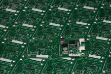
The boards arrived a day early. They'll be in the mail today. Thank you to all who pre-ordered.
I assembled one board. With 15 V in, 5.0 V out at 1.55 A the regulator IC barely gets warm. On the top of the IC package, I measure 31 degrees C. I'll post more results as I have them, but for now I'll focus on getting my website updated with design documentation of the filament regulator.
~Tom
Folks,
The boards arrived a day early. They'll be in the mail today. Thank you to all who pre-ordered.
I assembled one board. With 15 V in, 5.0 V out at 1.55 A the regulator IC barely gets warm. On the top of the IC package, I measure 31 degrees C. I'll post more results as I have them, but for now I'll focus on getting my website updated with design documentation of the filament regulator.
~Tom
Attachments
Soldering the IC is actually pretty easy once you know The Trick™
The Trick is to arm yourself with a good soldering iron with a big tip (big thermal mass). I use a 6.3 mm wide chisel tip on my Metcal. Then cover the thermal pad on the board with solder. Use enough to plug the thermal vias and leave a light coat on both the top and bottom side of the board. Then lightly coat the DAP on the IC with solder. "Lightly" is key here. Use enough to cover the DAP but not so much that it forms a bump. Apply flux to the thermal pad on the board and the DAP. Place the IC on the board and heat up the thermal pad from the bottom. Once the flux has boiled off you should watch the solder melt and the IC center itself on the footprint thanks to the surface tension of the solder. Once that happens, remove the soldering iron and let the board cool down.
You can also use a heat gun with a small diameter nozzle, but I find the heat to be easier to control with a soldering iron.
~Tom
SMDs such as resistors are easily soldered by placing a small bump of solder on one pad. Hold the resistor with tweezers, heat the solder bump and when it is liquid place the resistor in place. The solder will wick to it due to the heat transfer from the thermal mass of the pad and iron. As soon as the solder wicks remove the iron. Then solder the other pad.
SMDs such as resistors are easily soldered by placing a small bump of solder on one pad. Hold the resistor with tweezers, heat the solder bump and when it is liquid place the resistor in place. The solder will wick to it due to the heat transfer from the thermal mass of the pad and iron. As soon as the solder wicks remove the iron. Then solder the other pad.
That's my trick as well. Works every time. I will sometimes go back and clean up the first solder joint once the component is on the board.
~Tom
I spread flux on the pads, let it become tacky, place the resistor, melt a small amount of solder on the iron tip, and touch the tip to the pad and the solder flows right in. Obviously, you have to pin the resistor with something or it will be pulled towards the iron tip. I can do a lot of resistors quite quickly this way.
The DAP will be new to me. I'm looking forward to learning something new with this.
By the way, I got my boards today. If only my digi-key order were anywhere close to me right now...
The DAP will be new to me. I'm looking forward to learning something new with this.
By the way, I got my boards today. If only my digi-key order were anywhere close to me right now...
The DAP will be new to me. I'm looking forward to learning something new with this.
It's not rocket surgery. It does test your soldering equipment, though. Must .... have .... thermal .... mass....
By the way, I got my boards today. If only my digi-key order were anywhere close to me right now...
Boards are in as well. Look forward to populating over the next few weeks.
Nice! Yeah, I noticed all US shipments except one were delivered today (11/23). Let me know how assembly and test goes.
I should also note that due to the general craziness of Christmas/Festivus/"The Holidays"/Winter Solstice I will ship the last order of 2011 on Tuesday December 13. Any orders placed after that date will ship in early January. Just keep this in mind in case you want Santa to bring you boards for Christmas. I'll be around and follow DIY Audio, though.
~Tom
Last edited:
So far I've tested 5.0 V @ 1.5 A; 6.3 V @ 1.2 A; 7.5 V @ 1.25 A; and 7.5 V @ 2.5 A using the values in the Known Good BOM spreadsheet. The output voltages come in within 1~2 % of the target value, which is about as good as one can ask for. The output impedance looks good and indicates better loop stability than I was seeing with my setup a few months ago due to better choices of output capacitors. I still need to look at the transient response, though.
I'll post pictures when I have a little more data together.
~Tom
I'll post pictures when I have a little more data together.
~Tom
I'm waiting on parts to build a 2.1V regulator for use with 4P1L. Using 2.1V and driving both ends of the filament with the center tap common will reduce the voltage delta across the entire filament. This may or may not have any bearing on actual performance of the 4P1L.
It has lower distortion. See my post re 4P1L line stage....
I should try the 2.1V, however I need to run it a lower filament current to minimise distortion and microphonic feedback. Can you adjust the current manually in your regulator?
The filament obeys Ohm's law regardless of what voltage/current source is connected. So if you want lower current in the filament, just lower the output voltage of the regulator. If you want the current to be 10 % lower, make the output voltage 10 % lower. As others have pointed out already, this can be done by changing R1, R2.
The output impedance of this regulator is very close to zero Ohm. In other words it's about as close to an ideal voltage source as you can get. I'll post plots of Zout over the weekend.
~Tom
- Home
- Vendor's Bazaar
- Universal filament regulator