Alastair,
You are correct with the nipple distortion..I have found that a low value of resistor on the grid of the PI is an issue. I now have 120K in this postion.
The effect sounds like the speakers are out of sink with each other..a bit like some else is singing along very quietly...quite a strange effect..
This also gives reduced power available due to the overriding distortion effecting the OP at higher powers.. So your right again...LOL
Just for fun the 1813 vishay caps (output to 6C33C) give a tighter base with the Obbligatos in the interstage position..may not be of interest..")
Regards
M. Gregg
You are correct with the nipple distortion..I have found that a low value of resistor on the grid of the PI is an issue. I now have 120K in this postion.
The effect sounds like the speakers are out of sink with each other..a bit like some else is singing along very quietly...quite a strange effect..
This also gives reduced power available due to the overriding distortion effecting the OP at higher powers.. So your right again...LOL
Just for fun the 1813 vishay caps (output to 6C33C) give a tighter base with the Obbligatos in the interstage position..may not be of interest..
Regards
M. Gregg
Final comment on the caps,
All now as in post #723,
0.47uF 400V 716 orange drop OP to 6C33C and 0.22uF 630V Obbligato gold in the interstage cap position. (Works well with most sources)..
Cheap and works very well...(good low level detail)
With the change of PI grid resistor (metal film) is 120K..
No comments on the high end stuff..each to his own...
I guess its time to look at other things..LOL
Regards
M. Gregg
Sounds like you been having lots of fun!
Yes--That resistor helps with distortion at the high signal-levels, to help even more, a greater supply volts to the PI would be good, so the 'headroom' before clip/dist would be higher...
A different valve for the PI would be another option....
Yes--That resistor helps with distortion at the high signal-levels, to help even more, a greater supply volts to the PI would be good, so the 'headroom' before clip/dist would be higher...
A different valve for the PI would be another option....
Its good to play with different type of capacitors , but not overdo it , it will became "cheaty" , there is still many experiments to do , to "improve " the sound of thge amp .OK just an update,
The toroids now have cork pads under the rubber pads made from cork tiles..
Result reduced Tx noise (mechanical)..
(Tx under rated no heat issue)
The 0.22 interstage cap was changed just for a laugh to Obbligato 630V <<(seem to like violin don't know why)
I would never have tried them except I was interested in price Vs performance...Compared to jupiter HT in this part of this circuit..Well yes different..for the price you have got to try these
Switched on Jessie J and goose bumps..LOL
So as it stands now for a laugh orange drop to Op tubes and as above..LOL
The saga continues...
Regards
M. Gregg
Help...
I have had to listen to the whole collection of the jackie albums..
The disco 3 CD is on again for the 3rd time...Wife has taken over...9Hrs today...how do I get control of it.. 
Could do with a remote power button.. when the handbag bear is on the speaker its hers..hows that work then??
Regards
M. Gregg
I have had to listen to the whole collection of the jackie albums..
The disco 3 CD is on again for the 3rd time...Wife has taken over...9Hrs today...how do I get control of it..
Could do with a remote power button.. when the handbag bear is on the speaker its hers..hows that work then??
Regards
M. Gregg
Maby you can use a PI solution like mine , EL84 triode powered with +390V , AC coupled with the previous stage , with AC coupling I can easily set the bias by changing the value of the bias resistor which is very important , it drives easily 12 PL36 in my Futterman OTL amp , without the need of Fet driver onto the output tubes . Or you can use the 6V6 or 6L6 as you said .I think,
If I was going to mod then in order of preference they would be:
Increase the B+ on the PI to 500V
Use Fet driver direct onto 6C33C tube grid
Change PI to 6V6 or 6L6
Taking in to account that the amp is built then these are questionable..
But...
Regards
M. Gregg
Xiider,
There have been may more changes..I think you have to regard this as an ongoing fun project..
The schematic you have posted is not my design, however the coupling caps to the 6C33c grids are 470nf not 220nf..the bypass caps on the 6C33c cathodes are 4700uF electrolytic..these are now bypassed on mine with a fet zener circuit to gain more power..
I think you should at least give yourself the option for fixed bias windings etc. The power is very low compared to fixed bias..You can regard the output stage as a mix and match to try different things,,
I now realise that the OTL is not as scary as people make it out to be, as long as you take correct precautions..
I only just noticed this post..
My OTL has now had many modifications...
The number one thing that people don't tell you is to not use the simple power supply with just two caps in the power rails..If I had known this I would have used chokes after the caps Value 2H 2A. 0.5ohms, Other values may give better results..then some caps just to keep it stable..From what I can tell ALL otls suffer from this unless you have speakers that are not sensitive..When people change over to sensitive speakers the hum can be an issue..
I suppose if you think about it, it makes sense even a SE amp will not work with out a choke...LOL
Regards
M. Gregg
Last edited:
Just for interest,
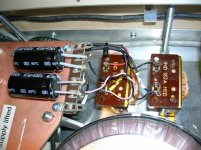
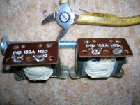
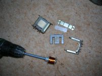
I removed one of the PSU caps that was an additon across the +/- rails and used the space for these..
A couple of chokes wound for a test and give a reduction in Hum..
This was/is just a test and it seems to work well..
OK the wire may need a rewind to reduce the DC resistance but they work quite well..
Regards
M. Gregg
Attachments
Last edited:
I guess,
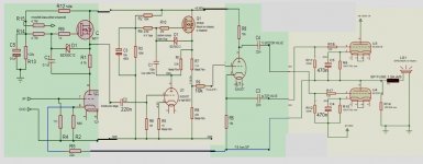
I should also mention that in the above diagram the resistor R9 on the PI grid is now at value 120K to reduce the nipple distortion as discussed by Alistair..
The power is high enough for me but YMMV..
If the resistor you are refering to is R4 on the 2nd stage CCS it 4.7M connected to the gate stopper 2nd stage FET..
Regards
M. Gregg
Last edited:
Ok, i have sensitiv speakers (91), so i probablydont need more power. At the moment I´m just getting like >6W from my Amp.
What PSU do you used? If I remember rightly, there was something about the PSU from Tim Mellow. I think i will remake the schematic.
The interesting point with this amp is it can be modded to try different things..The FET Zenner (Mozener) makes a difference across the cathode bypass on the 6C33C's..There are other mods I have done to the PI driver 2nd stage.using LED's etc...
With sensitve speakers you must smooth the power rails well.
I used the Tim mellow supply without the additional bits for the bias so its just a split winding output Tx with a UF soft recovery bridge and I used a 470 ohm resistor on the CT between the Tx ct and the cap Ct..the value of this resistor does make a difference on my system.
So the Tim Mellow PSU on its own is not going to cut it with sensitive speakers you will need to use a double cap with a choke in between..on each rail.
Regards
M. Gregg
Just for interest,
I tried LED's in the first stage cathode these are now replaced with a 3W Mills non inductive resistor 680 Ohm. Preferred part..
I do have LED and diodes in the cathode of the other section..
The diagram was also just for guidance so ignore the pin out numbers for the tubes..and just write them in from the data sheet..
I am also trying Hovland supercaps in the coupling between 1st and second stage. (220nF). A first listen...
I do use my amp with one heater alot of the time...and its still playing for 4hrs + every day (just swap over once a month to the other side to equal the wear on OP tubes).
I have increased the number of holes in the top plate for the cooling..always thinking of ways to improve..
There is more however I'll shut up for now...
Regards
M. Gregg
I tried LED's in the first stage cathode these are now replaced with a 3W Mills non inductive resistor 680 Ohm. Preferred part..
I do have LED and diodes in the cathode of the other section..
The diagram was also just for guidance so ignore the pin out numbers for the tubes..and just write them in from the data sheet..
I am also trying Hovland supercaps in the coupling between 1st and second stage. (220nF). A first listen...
I do use my amp with one heater alot of the time...and its still playing for 4hrs + every day
(just swap over once a month to the other side to equal the wear on OP tubes).I have increased the number of holes in the top plate for the cooling..always thinking of ways to improve..
There is more however I'll shut up for now...
Regards
M. Gregg
Last edited:
Xiider,
There have been may more changes..I think you have to regard this as an ongoing fun project..
The schematic you have posted is not my design, however the coupling caps to the 6C33c grids are 470nf not 220nf..the bypass caps on the 6C33c cathodes are 4700uF electrolytic..these are now bypassed on mine with a fet zener circuit to gain more power..
I think you should at least give yourself the option for fixed bias windings etc. The power is very low compared to fixed bias..You can regard the output stage as a mix and match to try different things,,
I now realise that the OTL is not as scary as people make it out to be, as long as you take correct precautions..
I only just noticed this post..
My OTL has now had many modifications...
The number one thing that people don't tell you is to not use the simple power supply with just two caps in the power rails..If I had known this I would have used chokes after the caps Value 2H 2A. 0.5ohms, Other values may give better results..then some caps just to keep it stable..From what I can tell ALL otls suffer from this unless you have speakers that are not sensitive..When people change over to sensitive speakers the hum can be an issue..
I suppose if you think about it, it makes sense even a SE amp will not work with out a choke...LOL
Regards
M. Gregg
I've not built the OTL design by AlistairE that you are describing, but I have built the OTL design by Tim Mellow, and even with my Lowther DX3 drivers, which have a sensitivity of 98dB, I hear no hum at all even with my ear right up against the speaker. I'm using just a simple power supply, like in Tim Mellow's circuit (except that I have 4400 uF per side, comprising two paralleled 2200 uF 200V electrolytics). I wonder if there could be some other factor at play in your amplifier that is causing hum?
Chris
I have spoken to quite a few people now and they have built different OTLs and yes they also have hum with some speakers..
With the chokes the Hum is very low ear to the speaker.. And even with the pre section B+ turned off with no chokes just the OP stage there is hum..so its definatly the OP stage and its not the heaters..
Does the tim Mellow have some kind of hum cancel circuit possibly tied to the driver stage? Even with no Ct connected the same is still true..
The only other thing is Tim mellow has heaters connected to the power supplies and lifted via + and - 150V rails...
However I think this is not relevant..or the chokes would not make a difference...
Regards
M. Gregg
Last edited:
Sorry for the late response )=
I sat down and remaked the schematic:
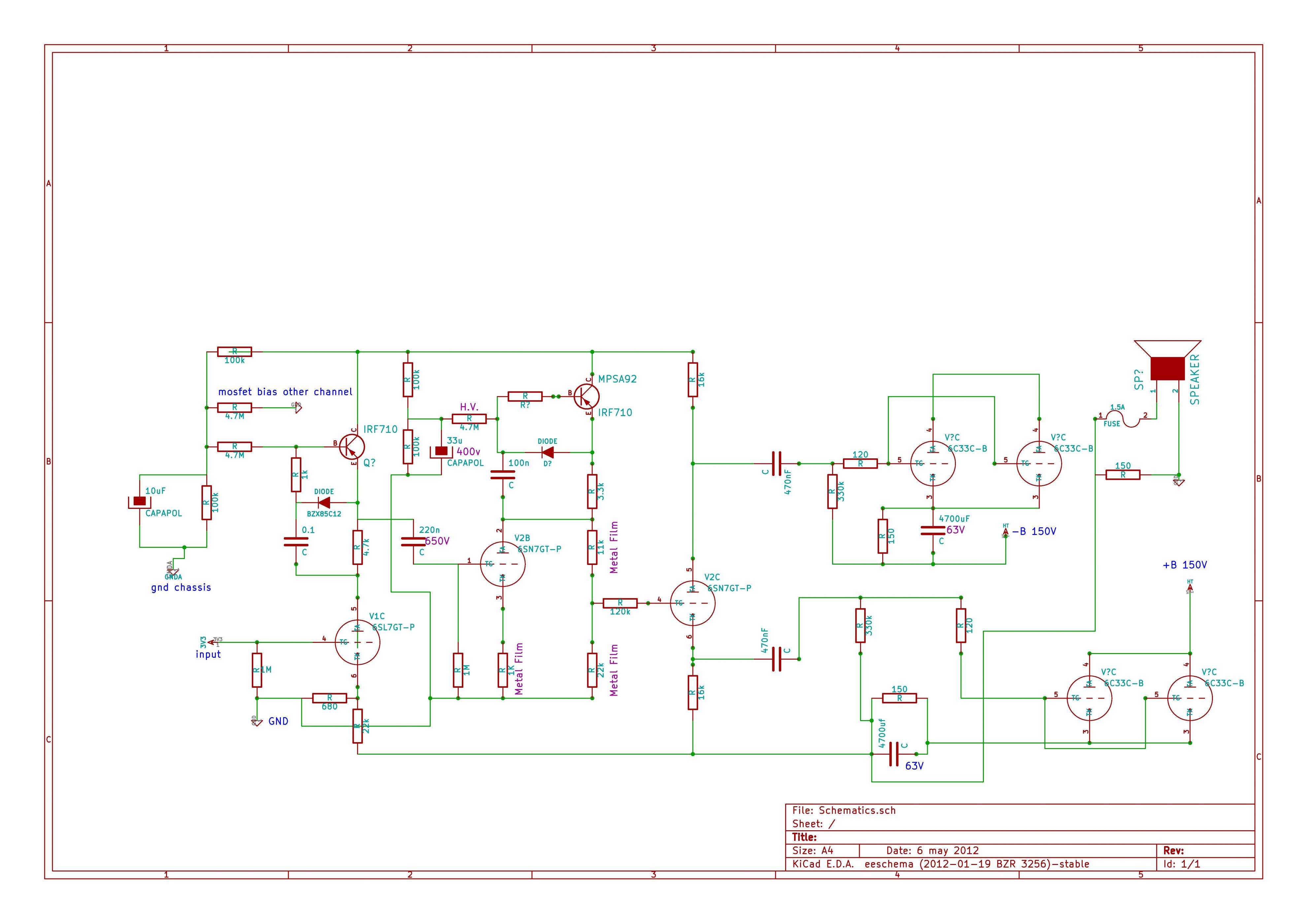
I forgot to notice that the resistor below the fuse is a 5W one.
You used this PSU: http://diyaudioprojects.com/Forum/download/file.php?id=2101 am i right?
I dont need the 146V and the -430V part anymore. Can i just remove them ( C6+R21 and R31+R32+C16+C17)? And you removed one of the Caps (C12-15) and replaced them with some Cokes.
How difficult would it be to replace the transformer with a 2x 115 one? I only saw 115 ones no 120..
I sat down and remaked the schematic:
I forgot to notice that the resistor below the fuse is a 5W one.
You used this PSU: http://diyaudioprojects.com/Forum/download/file.php?id=2101 am i right?
I dont need the 146V and the -430V part anymore. Can i just remove them ( C6+R21 and R31+R32+C16+C17)? And you removed one of the Caps (C12-15) and replaced them with some Cokes.
How difficult would it be to replace the transformer with a 2x 115 one? I only saw 115 ones no 120..
Attachments
- Status
- This old topic is closed. If you want to reopen this topic, contact a moderator using the "Report Post" button.
- Home
- Amplifiers
- Tubes / Valves
- Vacuum Tube OTL power amp!!