Well, Ive been running the amp now with 6C33C --wired single-cathode with the feedback as in the last diagram.
Its sounds really nice, the FB helping tighten the bass and this shows through on movie soundtracks, where there is a very deep bass...
I'm not sure the longterm effects of running a 6C33 only on 1 cathode, what effect is this having on the unused cold cathode over time...?
Guess you could arrange the heater-supply so as to turn off 'either or' and use them alternately....
Last edited:
Are the values for the feedback you are using the same as quoted before ie 33K / 470K ?
The other way for the heaters would be to use a flip flop circuit that changes the heater over either on start or power down to equal the wear + retentive both switch / push button so the amp always starts in power save mode. Or as you say A/B/Both.
I guess it will be a while before I get the parts togeather. LOL
Regards
M. Gregg
Just as an idea,
Electro-Mech solution
Page Not Found | OMRON Industrial Automation
Haven't given it enough thought at the moment. Also perhaps a minature version with a simple on / off push button so the off button toggles the relay. Could also be done with Cmos.
The switch is easier!
Regards
M. Gregg
Electro-Mech solution
Page Not Found | OMRON Industrial Automation
Haven't given it enough thought at the moment. Also perhaps a minature version with a simple on / off push button so the off button toggles the relay. Could also be done with Cmos.
The switch is easier!
Regards
M. Gregg
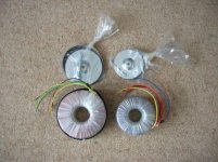
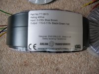
Yes, This is the spec from their website --
VA: 400 VA.
Power: 400VA Toroidal Transformer
Secondary: 115-0-115vac Bifilar wound connected in series (200mm flexible leads 16awg)
Primary: 230vac (200mm flexible leads 16awg)
Core: Unisil: M089-27N
Copper: OFC 99.99%
Dimensions: 145 x 65 (mm)
Faraday shield: Electrostatic screen with earth lead
EMI/RFI Shield (2 layers of GOSS steel band)
Standard: EN61558-2-6
Fixing: Standard Hardware 2 pads + steel dish washer
It does look a great Tx, Might even get one myself for a Mk II one day....
I guess there's scope with this Tx to supply 4 6C33C per channel if you wanted to go bigger, definately fine for just the two per channel!....
--But then you're getting Bigger and Hotter, adding complication, something I'm thinking you are trying to avoid!
Ive found that a good, stout power-supply for the O/P stages for Any OTL is one of the deciding factors for good sound...
Weak saggy supplies need not apply!
The 'HT' trans (+B) you're looking at their 'VAL1601' Guess you could use this, although its rectified voltage would be well over 400, and its current rating well higher than you'll ever need for the pre-amp stages--Guess you can 'lose' some volts over CRC filter and maybe a valve rec though....
I use the simple 'Pre-Amp' 250V 100mA and 6.3V 3A from 'Maplin' This gives me 350V rectified, (SS rec.) which is fine...
Last edited:
The 'HT' trans (+B) you're looking at their 'VAL1601' Guess you could use this, although its rectified voltage would be well over 400, and its current rating well higher than you'll ever need for the pre-amp stages--Guess you can 'lose' some volts over CRC filter and maybe a valve rec though....
I use the simple 'Pre-Amp' 250V 100mA and 6.3V 3A from 'Maplin' This gives me 350V rectified, (SS rec.) which is fine...
I have a maplin newton pre Tx..LOL
I agree the B+ is a bit high.
Should have looked closer. VAL3555 would be closer.
Just thinking about using all toroid.
Thoughts at the moment (may change) is to sandwich TX's on the bottom with EMI shielding and using the top as the pre/ power.
Might put one TX on the top to reduce the footprint. Perhaps duct the air with holes at either end of the chassis.
Regards
M. Gregg
Just a thought,
If the ducting created by mounting levels was a sideways "U". I could mount R9 & R10 on a heat sink in the middle of the "U" i.e. the bend in the air path. I might be able to drive the ducted air with the heat from the resistors.
So if the toroids were mounted on aluminium plate bolted onto birch ply with large holes e.g. 40-50mm with a cork insulator pad open at one end. The other side of the ply covered with checker plate for the base + holes finger protection this would reduce vibration and give a stiff base.
That would give venting for the air ect as the first part of the "U". Follow with vertical heat sink + resistors to the top section. Capacitors in a separate partition (maybe).
Just thinking out loud.
As you say you could increase the number of 6c33c's and switch in!
Regards
M. Gregg
Just a pic,
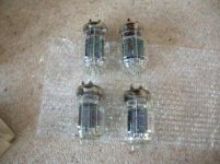
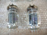
Got the 6C33c-B's today from Russia. Only took 2 weeks!
Starting to collect the parts..going to take a while.
Just for fun
")
Regards
M. Gregg
Just another thought,
A 6SN7 is two 6J5's in a single package.
So I guess a "12ax7 strapped" each side of a 6sn7 gives the tube line up.
Just a few thoughts
Alastair,
Is your IRF830 on a heat sink?
Regards
M. Gregg
Attachments
Ah--Hi M. Gregg!
Hmm--Where did you get '12AX7 Strapped' from--Never used the 12AX7 as its a personal hate of mine!
--Although, as its Sorta the 9-pin 'equivalent' of a 6SL7 you could use that instead...
For the valves, I used 6SL7 for the first stage, 'Strapped'. I guess a similar 9-pin high gain triode like your 12AX7 would be OK.
Personally, I like the 6SL7 as it can be used at pretty low currents and voltages and still give excellent sonics.
--This is moderately important, as Ive set the anode-volts of this valve at around 115/120V to allow direct, 'DC' coupling via the 470K to the phase-splitter valve.
--This gets rid of the coupling-cap and the self-bias cathode-resistor/grid resistor, the concertina normally would otherwise have.....
Some of the 9-pins aint as good at very low currents/voltages IMO, but it looks as though the 6SL7 was 'designed' with this in mind,--although I may be wrong....
The 6J5 is as you say, Half a 6SN7, guess you could use a 6SN7, and use one half in each channel....
Guess you could always use the12AX7 / 6SL7 to serve both channels as well, I strapped and used two valves, as it was felt to keep the gain stages completely separate in each channel is best....
--Keeps the crosstalk possibility from each channel to a minimum, but there's no real reason you couldnt use just the one valve for both channels.
The IRF830 has a very small heatsink, but does get a little warm, If you have a metal chassis, merely bolting to that will be more than enough, It doesnt dissipate much, as the SL7 only has less than 1mA flow, and the 22K to ground only flows around 5mA...
6mA at 220V gives 1.32W dissipation on the MOSFET,--So, not much to worry about.....
C6 runs at 120V or so, and a part having around 200-250V will be fine, although you could use a 350V part just in case the parallel resistor went O/C, it wouldn't spill its guts everywhere!
I'm using a standard ordinary electrolytic here....
Let us know how you get on!
Last edited:
Alastair,
Just a quick question after looking at another thread!
How have you hum bucked the heaters of the 6C33C's?
If they are in series ie four heaters per Tx heater winding.(one half of the tube in series) on one Tx winding the other half on the other Tx winding. So you can switch one winding off.
I guess raise the mid point of each chain with a voltage divider from B+, however B+ is +/- supply. Or is the chain connected to gnd as in the Tim Mellow circuit?
Or is it more like "top (B+)" 6C33C on one winding bucked from B+ and "bottom (B-)" of the c633c's bucked from B-.
With series parallel heaters on each winding / switch out one parallel section top and bottom?
Regards
M. Gregg
Last edited:
On closer inspection of the Tim Mellow otl.
The top 6c33c (On B+) heater chain is connected mid point to Gnd.
The bottom 6C33c (On B-) heater is connected to -150V mid point of chain.
This would seem to show:
"top (B+)" 6C33C on one winding connected to GND and "bottom (B-)" of the c633c's connected to B- 150V.
With series parallel heaters on each winding / switch out one parallel section top and bottom for reduced power?
I am supprised that no divider is shown for the heater lift, just direct connection?
This seems to follow the same topology for V1 -2 & 3..
Ref link Tim Mellow OTL
http://www.diyaudio.com/forums/atta...8124538-otl-designed-tim-mellow-4-6c33c-1.pdf
Regards
M. Gregg
Last edited:
Anders,
What circuit are you refering to?
I am refering to that one.
//A
I am just building at the moment,
However I can only assume the values are to set the DC coupling voltages between U1 & U2. R15 (4.7 Meg) and D1 set the voltage at that point.
Another question for Alastair I guess.
Then again as you say perhaps its time to build another one just for fun!
Regards
M. Gregg
However I can only assume the values are to set the DC coupling voltages between U1 & U2. R15 (4.7 Meg) and D1 set the voltage at that point.
Another question for Alastair I guess.
Then again as you say perhaps its time to build another one
just for fun!Regards
M. Gregg
Bappe--
R13 Is 100 Kilo-ohms.
--It serves no other purpose except as 'Gate-Stopper' Ive always used a nice big value for MOSFETS, due to their inherent oscillation tendancies....
100K works for me, --Use what you feel is good....
The Current through the tubes, U3/4 is around 180-200mA This can be altered if desired by changing the value of cathode-resistors, You may feel this is needed if for instance you have a different supply-voltage on the O/P stage....
Its important to keep the P. Diss of U3/4 to under 40W Max Idling to ensure longevity of sockets!
Ive kept the P-Diss of mine to around 20W per tube....
As to the heater-questions, Personally, Ive left the series-string of all valves floating--Ive done nothing 'Cunning' as M-Gregg has described!....
- Status
- This old topic is closed. If you want to reopen this topic, contact a moderator using the "Report Post" button.
- Home
- Amplifiers
- Tubes / Valves
- Vacuum Tube OTL power amp!!