PSU is completely standard. a SS Bridge-rec, after a large toroid I had floating round, I think it was an Isolating transformer...
I do have large 'RIFA' screw-term 3300uF 200V leccy-litics in each 150v rail, de-coupled by a couple of 10uF plastic caps...
The 350V supply is from a separate 'Maplin' mains Tx with CLC filtering....
I do have large 'RIFA' screw-term 3300uF 200V leccy-litics in each 150v rail, de-coupled by a couple of 10uF plastic caps...
The 350V supply is from a separate 'Maplin' mains Tx with CLC filtering....
You will find some old Wireless World articles on OTL valve amplifiers here:
The Wireless World Archive
The Wireless World Archive
Yup--standard ss bridge, no 'snubbing' and no regulation
The choke on the 350V line is 10H and 100uF caps, and SS rec.....
")
Thank's again.
Regards
M. Gregg
Alastair another quick question,
What is the distance you have between the 6C33B's / distance to any Tx.
DO you use series heaters for each tube and parallel the two in the left and right or series all heaters in left channel / same in the right?
Each in series would give approx 4A per tube? 8A parallel.
I have seen someone mention neon protection for the speakers, do you have any thoughts on this?
Regards
M. Gregg
All 6C33 heaters series-wired, supplied by 25V 5A, x2 Tx, a two-secondary toroid supplying them.... The three Tx are mounted down the centre of chassis, on top of case, I had to run a strut under them, with a 'leg' down to the bottom to stop the cheapo case sagging!
--As I said, It aint pretty, Hence no pics! but its a reasonably safe and usable machine
There's about 2.5" between any 6C33 and any other tube/item. There's spacers under the sockets leaving a small gap between them and chassis, there's also a PC fan in the case, running from rectified 6.3V, running under the 6C33 sockets. Its very quiet, only running at half-speed or so, the air can pass through the gap by the sockets up the sides of the valves....
--Ive mounted the caps under the chassis, inside the 'box' feeling that these should be kept as cool as is possible.
Heat doesn't seem to be a problem, although I certainly wouldnt grab a tube after an hours playing!
Not heard of the 'neon' thing, but wouldnt have thought a neon would protect a speaker. The 1.5A a/s fuse is sufficient IMO. Ive never had it blow--Yet, and Ive done some daft stuff with it....
Ive used a number of different suppliers--mainly ebay--but also got some excellent ones -british made- from a radio-rally a year or so ago...
Stay away from Chinese sockets appears to be good advice given on these Forums....
Its important to use very heavy wires to connect the heater-conns with to act as heat-sinks, as these give the most trouble with contact--allegedly....
--I'm using some '15A Rubber-Covered' cable I got from a local Motor Re-winders....
Few more questions..LOL
Did you twist the heaters cables?
Next question,
U1 is 6sn7 "strapped" I assume you mean using both sides of the 6sn7 as one triode. ie. Anode to Anode, grid to grid cathode to cathode?
Not one half on each channel?
One more question,
What are the hottest components in the circuit "not the tubes"
R9, 10, and 14 come to mind. Any special precautions you have found with position?
Regards
M. Gregg
Yes, the heater runs are a twisted pair...
The 6SL7 is connected A-A, G-G, C-C,--ie, Paralleled out...
--Its a 6SL7, not SN7....
R9, R10 are the highest dissipation, I used standard 17W WW resistors.
R14 from speaker out to earth doesnt really get warm even.
The Phase-Splitter resistors need to be 2W at least as these get pretty hot, Nothing much else except the MOSFET gets warm really, and that is mounted on the case which is fine...
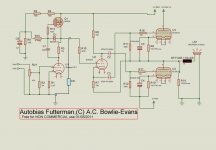
--Just noticed, Ive omitted a resistor in the schematic---
Need a 22K from top end of R3 to earth, (Joint between R3 and R16 to earth).....
The 6SL7 is connected A-A, G-G, C-C,--ie, Paralleled out...
--Its a 6SL7, not SN7....
R9, R10 are the highest dissipation, I used standard 17W WW resistors.
R14 from speaker out to earth doesnt really get warm even.
The Phase-Splitter resistors need to be 2W at least as these get pretty hot, Nothing much else except the MOSFET gets warm really, and that is mounted on the case which is fine...
--Just noticed, Ive omitted a resistor in the schematic---
Need a 22K from top end of R3 to earth, (Joint between R3 and R16 to earth).....
--Just noticed, Ive omitted a resistor in the schematic---
Need a 22K from top end of R3 to earth, (Joint between R3 and R16 to earth).....
LOL,
Like this?
Do you start the heaters first then time in HT or all togeather?
6SL7 --ECC83 did you try an 83 or do you prefer the octal?
Just for interest the neon circuit!
http://www.cincocoronas.com/nysva/images/25w_otl/25w_otl.pdf
Also how do they get round the heat from the 6c33 tubes, look very close to me?
Regards
M. Gregg
Attachments
Last edited:
Well,--
They are all 6C33C tubes.....
The 6C33C-B allegedly are more strictly made and tested versions but for all practical purposes and our use of 'em they are completely interchangeable (Read, Identical) with each other....
I have both versions. The only valve I ever had fail some years ago (because I hadnt burned it in properly...) was the alleged 'better tested' 6C33C-B part.
--Personally, I just think they tested a number from various batches and shoved the suffix 'B' on some, that had been subjected to more stringent testing.
So, IMO--It makes Zero difference whether its a 6C33C or a 6C33C-B valve....
--Apparently, there's even a 6C33C-B.EV type out there, But Ive never seen any--Doubt they would be much 'better' than a plain one to be honest!
If buying some, and if possible, Go for 'early month' numbers--apparently late 'month-numbers' were rushed through to make sure quotas were kept for that factory, Whether this is true or not, I have no idea....
Also, for this circuit, Dont discount the 6C41C to use as a low-power O/P version. (They are dirt-cheap too) They'll give around 9-11W and sound really as good as the '33 but need a Good Burn-In first, just like the '33 Have the advantage too of much less heat/power 'waste'
My choice of 'Octal' over 9-pin is just personal, I prefer the larger style and never really liked the 'ECC' series dual-triode valves...
Whatever output bottles you end up using, Burn Them In WELL before running 'em in an amp--Any Amp--Loads on this forum about how to and why....
Not sure of the 'Neon' trick--Still thinking of that one!
- Status
- This old topic is closed. If you want to reopen this topic, contact a moderator using the "Report Post" button.
- Home
- Amplifiers
- Tubes / Valves
- Vacuum Tube OTL power amp!!