Hey Chris,
link is on the first page of this thread, but Alastair has changed a few things, also introducing 6SN7 a few pages later:
http://www.diyaudio.com/forums/tubes-valves/189282-vacuum-tube-otl-power-amp.html#post2577375
link is on the first page of this thread, but Alastair has changed a few things, also introducing 6SN7 a few pages later:
http://www.diyaudio.com/forums/tubes-valves/189282-vacuum-tube-otl-power-amp.html#post2577375
Hey Chris,
link is on the first page of this thread, but Alastair has changed a few things, also introducing 6SN7 a few pages later:
http://www.diyaudio.com/forums/tubes-valves/189282-vacuum-tube-otl-power-amp.html#post2577375
Well, as was discussed again recently, one should be aware that the output power from such a design that uses self-bias in the output stage (the 150 ohm cathode resistors) will be very low in comparison with the output power achievable using fixed bias (as in Tim Mellow's design). As far as I recall, the measurements quoted earlier in this thread indicated only about 2 or 3 watts maximum output power. By contrast, Tim Mellow's design achieves about 25 watts.
Chris
Some experiments have shown me that for high efficiency and power and tube life, the load should be more like 200-500 Ohms when 6080 or a few of the larger regulator triodes are used. The load has to match the current and dissipation characteristics of the set of tubes in use. While a 10-20W amp can be made for 16 ohms with three 6080's, it is not a very happy amp. They were commercially used on some aircraft as audio amps running of a 400Hz 117V source with + and - voltage doubler rectifiers. The reason was weight saving, not audio considerations or tube life. While OTL tube amps for common speakers are fun and some beautiful commercial products as well as hobby products have been made, I give up on them for real use when I want the cannon of the 1812 overture. Maybe good for a headphone amp or pc speakers amp at a few watts. Just an opinion. I had some huge 900mA triple cathode graphite plate series regulators and even those sounded clean at a few watts, nothing was possible for the high power level I prefer except a sea of tubes. I changed my mind after trying this stuff out. Back to push pull pairs of 811's and quads of 6550's and 807's, and some day the pp 4-1000 sub amp. all pp, xfmrs.. no se. A horror to all golden ears!
Hey Chris,
Alastair claims that the amp has around 15W. He sounds like he knows what he is talking about.
Anyhow, Tim Mellows design seems to be easier to built, as the transformers are pretty much standard types.
When I hear that an amp sounds to bright, I always fear that is misses something at the other end of the spectrum. I am listening mostly to classical music and jazz, and I am quite allergic against a bodiless sound of i.e. a cello.
I am not at all afraid of resolution and the last thing I would like to build is a soft and colored sounding amp.
Any thoughts on my initial questions?
Heinz
Hey Chris,
Alastair claims that the amp has around 15W. He sounds like he knows what he is talking about.
Anyhow, Tim Mellows design seems to be easier to built, as the transformers are pretty much standard types.
When I hear that an amp sounds to bright, I always fear that is misses something at the other end of the spectrum. I am listening mostly to classical music and jazz, and I am quite allergic against a bodiless sound of i.e. a cello.
I am not at all afraid of resolution and the last thing I would like to build is a soft and colored sounding amp.
Any thoughts on my initial questions?
Heinz
There was some discussion back on this thread about the output power. (Look at post #517, and +/- around there.) There were some confusions concerned with peak-to-peak output voltage versus RMS output voltage being used in the calculations. I think once that was settled, the power output was established to be about 2 watts maximum.
It's not that surprising, really. To get the 25W that the fixed-bias output stage can achieve, you need a peak anode current of 2.5 amps. With autobias instead, and a 150 ohm cathode resistor, the current couldn't possibly reach that kind of level, and so the power output is bound to be way down. Anyway, the output voltage that was quoted back around post #517 was 11V peak-to-peak before clipping, which means about 3.9V rms, and hence about 1.9 watts into 8 ohms before clipping.
Chris
Regarding the power supply for the output tubes, most need bipolar 150VDC.
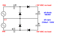
I have an good offer for 70-CT-70 VAC power transformer. With only a simple full wave rectifier i will only end up with approx 70*1.414 = 98 volts at no load, this is not enough. However, is a voltage doubler out of the question? Something like shown on the attachment.
With that doubler, i will get 70*2.828 = 197 VDC. I am allowed to drop 197-150 = 47VDC when amplifier is making 25W at output rms current of Ipeak 2.5A / 3.14 = 0.8A. So..
Electric Charge (Coulomb) = 0.8 * (1/50Hz) = 0.016 C
Capacitor size (Farad) = 0.016 / 47 = 0.00034 F or 340 uF. Since i'm charging two caps per rail, then i need at least 340 x 2 = 680 uF for one channel. Since i'm running stereo, i will need 680 uF x 2 = 1360 uF. I think 2200uF would be a good size then?
Can anyone immediately see if there's something wrong with my calculation and my schematic?
Attachments
With that doubler, i will get 70*2.828 = 197 VDC. I am allowed to drop 197-150 = 47VDC when amplifier is making 25W at output rms current of Ipeak 2.5A / 3.14 = 0.8A. So..
Electric Charge (Coulomb) = 0.8 * (1/50Hz) = 0.016 C
Capacitor size (Farad) = 0.016 / 47 = 0.00034 F or 340 uF...
You are allowing something like a 47V sawtooth ripple on a 197V supply, is that the idea? Sounds like a recipe for quite a lot of hum. Not to mention a lot of heating through losses in the capacitors.
I don't have a good answer for how to drop the excess voltage in a satisfactory way. As far as the voltage doubler idea is concerned, I should have thought you would be better off just connecting the transformer secondaries in series, grounding one end, and half-wave rectifying the top end (140V rms). That is two say, two half-wave rectifiers, one for the positive supply and the other for the negative supply. (So there would be approximately a current balance between the positive and the negative half cycles in the transformer.) Your voltage doublers are in any case half-wave rectified, so you would be no worse off. In fact I think you would be better off, not needing the doubling.
You would still have the problem of the excess 47V on each supply. I don't see a good way to drop that. I certainly don't think it would be a good idea having a huge sawtooth ripple on the capacitors.
Chris
I should have thought you would be better off just connecting the transformer secondaries in series
Do you mean getting TWO transformers and connect them in series? This kills the wallet. Also 140 VAC half wave rectified would only give me 140*0.707 = 98 volts.. Not to mention the offer is for only one transformer

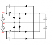
That 47V ripple will only emerge when i pull 25W from the amp. When idling it would be much less since the current demand is also smaller. I'm thinking of how class AB doesn't need as good filtering as class A. Am i thinking correctly here?
The attached schematic, assuming it works, should have even lesser ripple since it uses fullwave rectifiers for each rail.
Attachments
Do you mean getting TWO transformers and connect them in series? This kills the wallet. Also 140 VAC half wave rectified would only give me 140*0.707 = 98 volts.. Not to mention the offer is for only one transformer
No, 140 VAC (rms) will give 140 * sqrt(2) when half-wave rectified, which is about 197 V, on no load. (Assuming, of course, that you use a smoothing capacitor after the rectifier!) What happens when it is loaded will depend on the size of the load, the current supplying capabilities of the power transformer, and the size of the smoothing capacitor. Essentially you will get a sawtooth waveform. Each time the 140 V rms sinewave reaches its positive peak (at about 198 V) the voltage on the smoothing capacitor will be replenished to this level (minus the voltage drop across the diode). It will then decay down until it is replenished to about 197 V again in the next positive cycle. (I'm assuming here for simplicity that the power capabilities of the transformer are not limiting the ability to recharge the capacitor to the peak voltage again.)
The full-wave voltage doubler is certainly another option. I'm not sure if that would be better or worse than a half-wave without doubling, as described above.
Chris
An externally hosted image should be here but it was not working when we last tested it.
Hi,
@Jack: That look like the Mckowski (spelling?) circuit from Audio Anthology, right?
Anyhow, guys, forgive me if someone mentioned it before but the main supply for the output tube is of utmost importance. By extension so is the power transformer. So, you do not want any ripple there as this is what you're going to listen to.
Make an AC analysis of any OTL and you'll know.
Another interesting OTL circuit using 4 6336A (can be subbed by 6C33C) is the Taki OTL. There's an error in the schem but I'll point it out for you if needed.
Bottomline, any OTL is highly dependent on the PS of its output valves.
Ciao,
Hi,
@Jack: That look like the Mckowski (spelling?) circuit from Audio Anthology, right?
Yes, that's the Dickie and Macovski design. Audio Engineering, June 1954. Amazingly, it was done with those puny selenium rectifiers, and 300uF smoothing capacitors that would have been really high value for those days!
Chris
800VA is too much.. Most use 500-600VA.
However, having only one 120VAC secondary is not OK if you're aiming for bipolar 150VDC output. With this, your only option is a fullwave doubler and then virtual ground to divide the double output.
What's better is to have the TWO of the same isolation transformer (120V in and out) of around 250-300VA each. Then you can connect the secondaries in series.
Since we're on the topic of virtual ground (example: dividing 300VDC with 47K + 47K resistors in series so that the center becomes GND), is it feasible to applied for amplifiers? Since i think class AB amp tends to draw equal amount of currents from each rail, then in this case the system will be in balance?
OK I found the answer to my question. I would need two of those transformer .
$30 each not expensive but 2x800VA just over kill.
Greetings
You could get by with just one isolation transformer (120V in, and a single 120V secondary). You could then do it exactly like the Dickie-Macovski setup, except that your isolation transformer would keep everything isolated from the mains supply.
In other words, you would use two half-wave rectifiers, one for the positive supply (roughly 120 * sqrt(2) -> +170 VDC) and the other for negative (-170 VDC), and then the voltage doublers giving +340 VDC and -340 VDC. (These are voltages under no load, which will be a bit less under load.) As long as your smoothing capacitors are big enough, you can keep the ripple low enough, even with the half-wave rectification. We are not restricted to 300uF like Dickie and Macovski were in the 50's. And, of course, silicon rectifiers will do a much better job, with much lower voltage losses, than the selenium rectifiers they used. With a single 800VA isolation transformer you would get quite good results, I think.
Chris
that circuit uses so much NFB (cathode to output) to achieve linearity. The unbalanced voltage gain of the output is the u of the outputs. from the grid of the 2nd 12AT7 to output is unity gain. A chipamp (gain of 10) driven from the grid of the 2nd 12AT7 cut back 1/10 will provide the same result.
- Status
- This old topic is closed. If you want to reopen this topic, contact a moderator using the "Report Post" button.
- Home
- Amplifiers
- Tubes / Valves
- Vacuum Tube OTL power amp!!