So I have been working on a balanced 300B pp monoblock project for a while now with good progress, but am now a bit spooked by the much talked about 'blocking distortion' that occurs when grid current temporarily charges the cap of an RC driver. I haven't ruled out RC yet, nor an IT either, but a source follower for me is not an option.
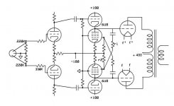
What I am looking at is a current sourced CF using the triode of a 6U8, and the pentode as the CS (see attached schematic).
In this circuit, feedback from the opposite phase causes the CS current to change inversely with the signal voltage, in effect negative resistance. This serves to keep the grid bias nearly constant in the CF, so the cathode does exactly 'follow' the input.
The magnitude of the current variation is set by the ratio r1/r2. In a test setup I used a dual trace scope to measure CF output subtracted from input, and adjusted r2 to produce a flatline. I found that a ratio of about 15 cancelled the error.
While this arrangement is very promising (output Z is <400ohm) it does add complexity, and somewhat complicates the power supply setup.
Any comments / critique from the learned folks on this forum would be welcome.
Attachments
You did not state why source follower was not an option. It looks like complexity is not the reason, given your circuit. Have you seen the work by Tubelab with 'powerdrive'? Morgan Jones used followers in his 'Chrystal Palace' PP amp, but they were tube if it is sand that you are allergic to.
Last edited:
You did not state why source follower was not an option.
When I first published the PowerDrive concept the reaction was mostly negative. That has slowly changed as other people actually tried it. There will always be people who do not want sand based life forms in the signal path. The phenomenon of PIM (phase intermodulation distortion) is most often quoted as the reason. PIM is a real distortion mechanism although PIM itself is hard to measure unless it is really bad. Its effects can be heard as a smearing or loss of high frequency detail. PowerDrive equipped amps seem to be regarded as "detailed".
A tube based cathode follower will never be as accurate as a source follower due to the higher transconductance of the mosfet. The cathode follower's shortcomings were well known back in the vacuum tube days. Google, and search this forum for "augmented cathode follower" to find the work by MacDonald in the 1950's to develop the "perfect follower". I have built it and it works so well that I made a big version to use as a 20 watt output stage.
The concept shown here may also work well. I never thought of it, and haven't tried it, but might when I get back to working with tubes.
Using the pentodes to make a negative R equal to the 300B grid resistor's R is darn close to a perfect follower. One could further add a tiny cap across r1 to null out the 300B grid capacitance too. If it were me, I would just use a small Jfet (with less negative V rail) in place of the pentodes for the same setup. A high value of r1 can shield the signal from the gate capacitance.
Another approach would be to bias the two 300B grid resistors thru a high L common grid choke, (or use two L windings on the same core for separate tube biasing) and delete the pentodes. This way the Rg resistors act like a constant current source themselves at AC, so there's no resistance to compensate. Or, for a single grid L and separate tube biasing, that could be done using separate regulated (or cap bypassed) bias voltages to separate 300B filament supplies.
Another approach would be to bias the two 300B grid resistors thru a high L common grid choke, (or use two L windings on the same core for separate tube biasing) and delete the pentodes. This way the Rg resistors act like a constant current source themselves at AC, so there's no resistance to compensate. Or, for a single grid L and separate tube biasing, that could be done using separate regulated (or cap bypassed) bias voltages to separate 300B filament supplies.
Last edited:
Or, for a single grid L and separate tube biasing, that could be done using separate regulated (or cap bypassed) bias voltages to separate 300B filament supplies.
300B bias can be adjusted also by varying of filament voltages. Such a way halves of 6C33C are adjusted successfully in many amps.
Maybe a bootstrapped follower? And, eliminate the first coupling cap too (or move it anyway). With the negative supply should be possible? High u tube for the follower, in this case.
ECC83_300B_fundamental_schematic_20080323.png (image)
Sheldon
ECC83_300B_fundamental_schematic_20080323.png (image)
Sheldon
- Status
- This old topic is closed. If you want to reopen this topic, contact a moderator using the "Report Post" button.
- Home
- Amplifiers
- Tubes / Valves
- 300B 'direct drive' using a 6U8..