Merlin, I'd be interested in anything you can remember about why the resistance needs to be finite.
I've just looked through my collection of LTP articles, and I can't find what I expected to find. I think I must've imagined it.
I may have got the wrong end of the stick when reading this paper many years ago and never re-read it (until now)- see the second article:
http://dl.dropbox.com/u/57831278/Balanced_Ouput_Amplifiers_Richards.pdf
CPaul, can you see this link to my graph?
http://dl.dropbox.com/u/57831278/CathodyneOutputZ.bmp
Thanks, Merlin, I got it.
Regarding "effective" A and K impedances:
It seems that you can't directly measure them. They are generally different from A and K impedances. They have no useful purpose except when Ra = Rk. And even then the sole value they have is to prop up a problematic model of the Cathodyne.
Regarding "effective" A and K impedances:
It seems that you can't directly measure them. They are generally different from A and K impedances. They have no useful purpose except when Ra = Rk. And even then the sole value they have is to prop up a problematic model of the Cathodyne.
I see what you're saying.
I know you get the benefit of gains of +/- mu/2 from this modified circuit. And the Zouts are the same. Of course here, the equal Z operation is irrelevant since the transformer coupling precludes anything but pure differential operation.
If we cap couple in parallel, are equal Z's still irrelevant?
2K2 LC damping not in the way of signal paths anymore..
Attachments
Last edited:
If you peruse articles or books from over the past 80 years on the topic of triodes, over and over again you’re going find the same expression for the impedance looking into the plate of an un(cathode-)bypassed triode: zp = rp + (1+µ)·Rk. This expression, which does not include the plate load, is in the Radiotron Designer’s Handbook, the Preisman paper on Cathodynes from 1960 (equation (1)), and even in books by that great Cathodyne Equal_Z’er, Morgan Jones. Note that where this equation appears, there is never any inference that it does not hold over the range of operation occupied by Cathodyne, where the plate load Rp is close or equal to that of the cathode, Rk. And yet…
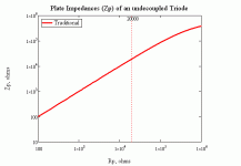
It’s worthwhile to look at a graph of Zp = zp || Rp. We can call Zp the “Traditional” plate impedance. Let’s consider a circuit where rp = 3K, µ = 30 and Rk = 20K. We’ll vary the plate load resistor from well below to well above Rk. Note that nothing special happens when Rp = Rk = 20K.
But the Equal_Z’ers will have none of this “nothing special happens” stuff. They claim that when Rp = Rk, the plate impedance is approximately 1/gm = rp/µ (100ohms in this case.) So I’ve shown this point on the graph below.
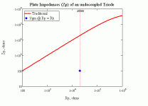
Here we see a sudden change by a factor of more than 100 from the Traditional value. Of course, this sudden and large change raises the question of the path the impedance followed to depart from and return to the Traditional curve. I can think of a few possibilities. Perhaps that value is held only when Rp precisely equals Rk:
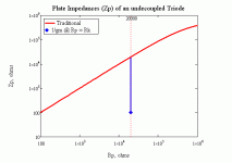
If so, to exhibit a 1/gm plate impedance, all real world Cdynes would have to have a perfect match between Rp and Rk. That is simply impossible. Maybe instead there is a region of finite width where the impedance 1/gm reigns:
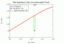
But if so, how wide is this region?
Or maybe the transitions shown above are too sharp, and they should be more gradual, something like the following:
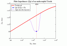
Whichever of these is the case, or even if something different obtains, Equal_Z’ers should be asking themselves not, “What are the boundary conditions?” but rather, “Where are the boundaries?” so they can avoid them like the plague. Anywhere impedance changes by a factor of almost 200, there are bound to be gross non-linearities and distortions galore. I wouldn’t want any of my circuits operating anywhere near these changes. But to avoid them, I’d have to know where they are.
Any of you Equal_Z’ers want to tell the rest of us where the boundaries are?
It’s worthwhile to look at a graph of Zp = zp || Rp. We can call Zp the “Traditional” plate impedance. Let’s consider a circuit where rp = 3K, µ = 30 and Rk = 20K. We’ll vary the plate load resistor from well below to well above Rk. Note that nothing special happens when Rp = Rk = 20K.

But the Equal_Z’ers will have none of this “nothing special happens” stuff. They claim that when Rp = Rk, the plate impedance is approximately 1/gm = rp/µ (100ohms in this case.) So I’ve shown this point on the graph below.

Here we see a sudden change by a factor of more than 100 from the Traditional value. Of course, this sudden and large change raises the question of the path the impedance followed to depart from and return to the Traditional curve. I can think of a few possibilities. Perhaps that value is held only when Rp precisely equals Rk:

If so, to exhibit a 1/gm plate impedance, all real world Cdynes would have to have a perfect match between Rp and Rk. That is simply impossible. Maybe instead there is a region of finite width where the impedance 1/gm reigns:

But if so, how wide is this region?
Or maybe the transitions shown above are too sharp, and they should be more gradual, something like the following:

Whichever of these is the case, or even if something different obtains, Equal_Z’ers should be asking themselves not, “What are the boundary conditions?” but rather, “Where are the boundaries?” so they can avoid them like the plague. Anywhere impedance changes by a factor of almost 200, there are bound to be gross non-linearities and distortions galore. I wouldn’t want any of my circuits operating anywhere near these changes. But to avoid them, I’d have to know where they are.
Any of you Equal_Z’ers want to tell the rest of us where the boundaries are?
But the Equal_Z’ers will have none of this “nothing special happens” stuff. They claim that when Rp = Rk, the plate impedance is approximately 1/gm = rp/µ (100ohms in this case.)
No, they say the effective plate impedance is approximately 1/gm. It's not the same thing. When are you going to let this go??
Now, what the heck is "effective" impedance?
It is the differential impedance split in the same ratio as the load resistors. Under balanced conditions -which is all that matters- it determines the bandwidth from either output. Nobody thinks the anode-to-ground impedance is 1/gm. As we have explained already. Ad infinitum.
In a letter to the editor in Linear Audio, Burkhart Vogel proposes a Cdyne model with a single "floating" voltage source in series with 2/gm. It too perfectly explains equal and opposite voltages in a balanced Cdyne. Now, if he were to calculate the "effective" P and K impedances in his model (he does not!), they would be about Rk/2 = Rp/2. His "effective" impedance would be very different from your preferred value.
Why should I prefer either of your "effective" impedances when they are so different, give wrong results in all but one specific instance, and I have impedances themselves to work with?
"Effective" impedance is so vague a concept that you can't even argue why the one you prefer is superior to one that Burkhart could have calculated.
Nobody thinks the anode-to-ground impedance is 1/gm. As we have explained already. Ad infinitum.
My claim (and to date, there has been no experimental refutation nor even a suggestion of an experiment that will refute it) is that the source impedances at the cathode and plate of a cathodyne are equal and low (roughly 1 or 2/gm) when the loads at cathode and plate are equal.
That last is from post 727.
Nobody?
In response to my question, what the heck is "effective" impedance:
Under balanced (ander other) conditions, the differential impedance is about 2/gm. It doesn't have to be "effective" to determine bandwidth - it just has to be impedance. "Effective" adds nothing and just confuses the situation.
It is the differential impedance split in the same ratio as the load resistors. Under balanced conditions -which is all that matters- it determines the bandwidth from either output.
Under balanced (ander other) conditions, the differential impedance is about 2/gm. It doesn't have to be "effective" to determine bandwidth - it just has to be impedance. "Effective" adds nothing and just confuses the situation.
Effective impedance doesn't apply to that model; you would need to split the single voltage source into two source equal to V/2. The 'effective' impedance of the cathodyne is just a shorthand notation; a quick and dirty mathematical trick; a sleight of hand. It's not meant to be universally applicable to the universe at large. It's not an established electrical 'theorem'.Burkhart Vogel proposes a Cdyne model with a single "floating" voltage source in series with 2/gm. It too perfectly explains equal and opposite voltages in a balanced Cdyne. Now, if he were to calculate the "effective" P and K impedances in his model (he does not!), they would be about Rk/2 = Rp/2.
Under balanced (ander other) conditions, the differential impedance is about 2/gm. It doesn't have to be "effective" to determine bandwidth - it just has to be impedance.
*sigh*
Yes. You are correct. You can use the differential impedance if you prefer. But some people prefer to consider one 'side' of a push-pull circuit when doing calculations. It's just a matter of preference and convenience which one you may want to use.
But that's not the point. The point is, your posts seem to be labouring on and on about a misconception that nobody has.
You personally may not *like* the concept of effective impedance, but you don't need to keep repeating that the plate-to-ground and cathode-to-ground impedances are different. We know.
Unless SY calls "effective" impedance "source" impedance, he clearly has this misconception. He spends almost half his Linear Audio article "proving" what you call "a quick and dirty mathematical trick."
It is with some bemusement that I see that you, who are so convinced that no one has this misperception, don't simply come right out and ask SY to set things straight. Is that not the obvious solution to what is bothering you? What reason could you possibly have for not doing this?
It is with some bemusement that I see that you, who are so convinced that no one has this misperception, don't simply come right out and ask SY to set things straight. Is that not the obvious solution to what is bothering you? What reason could you possibly have for not doing this?
- Status
- This old topic is closed. If you want to reopen this topic, contact a moderator using the "Report Post" button.
- Home
- Amplifiers
- Tubes / Valves
- phase splitter issue