Your measured results are exactly what theory predicts. They show that, taken in isolation, the cathode has lower impedance. Taken together (i.e. load both outputs equally), equal load gives equal voltage. Taken in isolation, the impedance at the anode is equal to the anode resistor because the valve anode resistance is huge due to the large amount of cathode degeneration.artosalo said:The results are as follows:
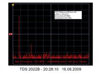
For interest, following the concertina, if a Williamson diff is used with a small amount of regenerative feedback from the split cathode resistor to the grids with a CCS to ground, the diff driver offers perfect capacitive balance for the concertina, proof is the near cancelling of the 2nd harmonic see trace....this only occurs with near matched tubes but illustrates how excellent this combination is.
Attachments
Quote:
Then, if the load impedance is too low - but equal at both outputs - the output voltages can be different.
This is entirely incorrect.
This is already clear and agreed.
What frequency are you measuring at ?
1 kHz. The reason is low (maybe 2...3 Mohms) input impedance of HP, not the capacitance I guess.
For interest, following the concertina, if a Williamson diff is used with a small amount of regenerative feedback from the split cathode resistor to the grids with a CCS to ground, the diff driver offers perfect capacitive balance for the concertina, proof is the near cancelling of the 2nd harmonic see trace....this only occurs with near matched tubes but illustrates how excellent this combination is.
This is also true for p-p output stages. One point on which there have been some errors in standard texts is the issue of class A versus class AB/B p-p output stages- it makes no difference, the load presented to the cathodyne is still equal.
Your measured results are exactly what theory predicts. They show that, taken in isolation, the cathode has lower impedance. Taken together (i.e. load both outputs equally), equal load gives equal voltage. Taken in isolation, the impedance at the anode is equal to the anode resistor because the valve anode resistance is huge due to the large amount of cathode degeneration.
This is easy to understand and agree.
If the outputs are loaded equally (and that is indeed the case with the cathodyne in situ), the source impedances at plate an cathode are identical and low (~1/gm).
I see that it is now demonstrated that equal loads will give equal output voltages and unequal loads will give unequal output voltages.
Therefore the actual output impedances can not be equal, even if they seem equal in case of equal loads.
If the output impedance at anode were 1/gm, then the small change at anode load would not cause essential difference at output voltage.
According to Langford-Smith (Radiotron Designers Handbook):
At anode: Rout = (µ-1)Rk where Rk = Ra
At cathode: Rout = (rp+Ra)/(µ+1)
Summary: Equal loads will give equal output voltages and unequal loads will give unequal output voltages.
This proves that output impedances are NOT equal.
I see that it is now demonstrated that equal loads will give equal output voltages and unequal loads will give unequal output voltages.
Therefore the actual output impedances can not be equal, even if they seem equal in case of equal loads.
Well, if the loads are equal, the output impedances HAVE to be equal, else the voltages would not be. With equal loads, the output impedances are not only equal, they are low. This can be seen by calculation of open circuit voltage divided by short circuit current (keeping loads equal), the usual definition of source impedance. This can also be seen by injecting equal (but opposite, to keep loads equal) test currents into the cathode and plate. And it can be verified by putting equal capacitances on each output and comparing rise times.
Please see my analysis and experimental verification in Linear Audio Vol 0.
I see the explanation given at Radiotron Designers Handbook (4th edition) more natural and convincing:
See 7.2 (ii) (B) page 330
The effective output resistance is different for the two output channels, since P (plate output) operates with current feedback and K (cathode output) with voltage feedback...... but this does not affect the balance at either low or high frequencies when the total effective impedance of channel P is equal to that of channel K. The same signal plate current which flows trough one impedance Zp also flows through the other impedance Zk, and if Zp = Zk then the two output voltages are equal.
See 7.2 (ii) (B) page 330
Don't underestimate coax capacitance. One is Easily fooled. Like RF in cables is able to create standing wave reflections that fight the tube capacitance. Anode in particular.
A test: A fast rise & fall 10Khz square wave with a dual input scope is a good check. One can also do the Lissajous test which is even more revealing. Do identical length coax connections to concertina upper and lower o/ps with exactly same type of coax and length, connect to scope Ch1& Ch2 same amplitude settings to get trace mid screen; and phase invert one channel and adjust shift to coincide.....one will find the upper concertina slews a bit more, which in other terms = slight phaseshift.
However, Sine wave amplitude is equal.
Some tubes may oscillate sensing capacitance, a 600R resistor in each O/p usually cures this.
I think <I've got this correct....disconnect one of the leads and everything becomes glaringly obvious !
richy
Don't underestimate coax capacitance.
No, I do not. I know this phenomenon.
Please refer to the Preisman article. Equations (1) and (2) and the surrounding text support Preisman's conclusions that "(cathode impedance) ... is much less than rp, and (the plate impedance) is greater than rp..."
The analysis Mr. Yaniger offers in his Linear Audio 0 article is unfortunately flawed. Plase see my reply to him at the Lnear Audiio Site under Online Resource in the Letters to the Editor section.
The analysis Mr. Yaniger offers in his Linear Audio 0 article is unfortunately flawed. Plase see my reply to him at the Lnear Audiio Site under Online Resource in the Letters to the Editor section.
I think the problem with understanding the cathodyne is that we normally think of output/source impedance as applying to a single output port, but then try to apply the same idea to a device with two output ports which affect each other. Because we don't realise we are making the 'single port' assumption, we don't realise that it doesn't directly apply.
If the two ports really had different and independent impedances then equal loading would give unequal voltages, as has been pointed out. For the cathodyne we either have to insist on equal loads (when we find a low impedance at both ports) or apply the idea of a Thevenin equivalent to a single port at a time. We cannot apply the Thevenin equivalent separately to two inter-dependent ports.
If the two ports really had different and independent impedances then equal loading would give unequal voltages, as has been pointed out. For the cathodyne we either have to insist on equal loads (when we find a low impedance at both ports) or apply the idea of a Thevenin equivalent to a single port at a time. We cannot apply the Thevenin equivalent separately to two inter-dependent ports.
You say that if the two ports have different impedances, then equal loading would give unequal voltages. But that’s not really the case. The equal and opposite voltages of the Cathodyne work regardless of whether the plate and cathode impedances are different or identical. This is because of one simple characteristic of a triode: as long as no grid current flows, the current into the plate is always equal (and opposite) to the current into the cathode. As long as the plate and cathode loads are identical, the voltages must be equal and opposite by Ohm’s law, regardless of the plate and cathode impedances.
I’m not sure why you say that equal loads on both ports leads to low impedances at both ports. Can you take me through that?
I’m not sure why you say that equal loads on both ports leads to low impedances at both ports. Can you take me through that?
If the two output ports had different (and independent) impedances then they would drop different amounts of voltage as the load impedance changes. This means that only one load impedance could result in equal voltage output, or possibly none at all.
By low impedance at both ports I mean that provided you keep the two load impedances the same you get the same voltage at each, which corresponds to a cathode follower type impedance. For example, a load of 1/gm would give a gain of 0.5 to both ports - implying an output impedance of 1/gm at both ports. Of course, this is stretching the concept of impedance to cover two related ports.
I think the basic problem is that engineers are so used to the concept of impedance that they insist on using it in situations where it is poorly defined or undefined.
But they do have different impedances. That is easy to see by simply setting the AC grid voltage to zero, and then inserting an AC current source first into the plate, and then into cathode. The plate voltage is going to be a lot larger, indicating a much higher impedance.
I agree that you can't strtech impedance to deal with two ports at once.
In a discussion like this, it's important to define impedance. I maintain that it is first a characteristic of two nodes. If you cause a current to flow between the two nodes, outside of the circuit under test, then the impedance of the node pair is the change in voltage between the nodes due to and divided by that current.
Do you agree? If not, what is your definition?
- Status
- This old topic is closed. If you want to reopen this topic, contact a moderator using the "Report Post" button.
- Home
- Amplifiers
- Tubes / Valves
- phase splitter issue