Some of your distortion will be coming from the diode
why? my 6H23 preamp so biased with a silicon diode sounds fantastic to my ears....
You probably won't have much distortion from the diode (that's something I've never been able to measure in a wide variety of circuits), but you may very well have unexpected distortion from grid current, which usually doesn't show up in sims. Many tubes of that class start showing significant grid current at Vgk < 1V or so.
Sorry, I misread the data. 6.44mV of signal across the diode is pk-pk, not pk or RMS. However, that would still give a few % of 2nd? (assuming a diode behaves something like a BJT Vbe? Vsig pk = THD 2nd % ?) Would be reduced because it is only a small part of the total signal. So 3.2mV gives 3.2% 2nd, but the diode signal is only 3.2% of the total so I make that about 0.1% 2nd due to the diode.
If the valve model includes grid current (some do, some don't) then you can check for distortion from this by adding some impedance to your signal source.
If the valve model includes grid current (some do, some don't) then you can check for distortion from this by adding some impedance to your signal source.
No, fortunately it is better than that. Most of the signal is developed across the grid-cathode so the diode only sees a fraction.Tony said:I realise that with the forward biased diode, you are limited to an input voltage of 0.7 volts peak if you are to avoid getting the grid in positive region
However, it is not the grid going positive you need to worry about. As SY says, grid current can start well before that. I seem to recall that the books warn that positive grid current can start anywhere between -1.5V and -0.5V, and the threshold varies not only from valve to valve (even of the same type) but can also change with ageing. I try never to have a grid more positive than -1V.
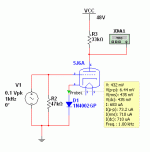
OK, I straightened out the SIM by using the Leach models and setting the coefficients such that the VI curves look like the 19J6 datasheet.
With the diode and the sections of the 19J6 in parallel, the THD% was 0.31%, with a 2K resistor per the Starving Student schema it was 0.052%
We're constrained by the 48V supply. Even more constrained by 19J6 becoming unobtanium.
With the diode and the sections of the 19J6 in parallel, the THD% was 0.31%, with a 2K resistor per the Starving Student schema it was 0.052%
We're constrained by the 48V supply. Even more constrained by 19J6 becoming unobtanium.
If you are very patient 19J6 appear on ebay from time to time, but who wants to wait a year before building an amp? You could consider UCC84 (or possibly UCC85), although these are not too common either. They are European 100mA heater valves, with E (6.3V) and P (300mA) versions too. The '85 is almost the same as a 12AT7, apart from the addition of a screen and different heater. The '84 was intended for cascode, so should be OK at low anode volts.
Little bit different -- a 1N4148 was used to bias the tube, and an LND150 Depletion Mosfet was used as a current source. I built one and tested it out:
I'll call it the "Ascetic Student" as it's starving but dignified.
An externally hosted image should be here but it was not working when we last tested it.
I'll call it the "Ascetic Student" as it's starving but dignified.
I'll call it the "Ascetic Student" as it's starving but dignified.
I don't know, it doesn't sound good to me. Starving but dignified belongs more to the 'artistic' family. An ascetic would never say 'I'm starving' (too proud for that) whereas artist and students have no problem declaring themselves so. Besides, ascetics are more masters than students.
Another point to have in mind is that an ascetic would probably have no need for a tube preamp.
I don't think ascetics have a humble opinion of themselves but it's true they're skinny. The 'starving' tag, nah, they wouldn't like it. An ascetic would look you in the eye and smile, knowing he's well fed. Spiritual richness makes you pretty wide.
Of course this has nothing to do with the name of your amp (it's your call).
Of course this has nothing to do with the name of your amp (it's your call).
If you are very patient 19J6 appear on ebay from time to time, but who wants to wait a year before building an amp?
19J6 is the same as the 6J6/ECC91 tube, of course besides the heater, isn't it? You can buy the latter one for less than € 5 in Europe!
Best regards!
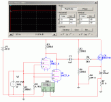
Made a couple of changes -- R1 =55k, R5 = 2k2, R3 =110k. Did away with the CCS. The output cap is an Elna Silk 220uF/50V, the coupling cap that shown in the design 0f 100nF.
Changing R3 biased up the MOSFET a bit higher, while loading the amplifier a bit more. Gain is 19dB. The 5% THD is ~5V out.
The above is with the 20EZ7 -- filament voltage is spot on at 20V.
Changing R3 biased up the MOSFET a bit higher, while loading the amplifier a bit more. Gain is 19dB. The 5% THD is ~5V out.
An externally hosted image should be here but it was not working when we last tested it.
The above is with the 20EZ7 -- filament voltage is spot on at 20V.
I looked into the 20EZ7 when I was designing a low cost guitar amp using a series string heater circuit. Although the 20EZ7 can sometimes be found for under $10 it is rather rare and was used in a few vintage guitar amps so it will disappear like the 19J6 as soon as someone starts using it in a published circuit.
- Status
- This old topic is closed. If you want to reopen this topic, contact a moderator using the "Report Post" button.
- Home
- Amplifiers
- Tubes / Valves
- Low voltage 12AU7 (19J6) -- re "starving"