Typically, receiving tubes are safe with plate voltage higher than 30-100V, or 1/4 to 1/2 of Vg2. Transmitting tubes are typically higher, of course.
As shown, the tube can never draw excessive screen current due to the large series resistance. However, this affects distortion and makes the input impedance particularly bizarre, because as the tube goes into saturation, screen current shoots up, screen voltage falls and miller effect comes into play on Cg1g2. Effectively, the amplifier slows down as it goes into saturation, which is undesirable.
I wonder why the designer chose 12BY7 over a more suited pentode like 6AU6, or a triode such as 6AV6.
Tim
I wonder why the designer chose 12BY7 over a more suited pentode like 6AU6, or a triode such as 6AV6.
Considering the designer was Stu Hegeman, you can be certain he had good reason. An obvious fact is the high gm of the 12BY7. That high gm provides resistance against slew limiting. The Cit. 5 employs Mullard style circuitry and a good deal of GNFB is present. Slew limiting is always a concern under those conditions. A possible tweak to the Cit. 5 is employing an ECC99, instead of a 6CG7/6FQ7, as the LTP. Stu didn't have access to the '99, with its high gm, back in the 1960s.
IIRC, the graphic is not error free. Check Jim McShane's site out for info. on tubed H/K Cit. units. Jim's expertise in this area is unrivaled.
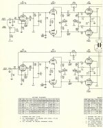
I believe your schematic in incorrect. Here is a partial scan of an original HK document. Notice the voltage chart in the lower left. It calls for 145v on the plate and 140v on the screen. And the screen bypass capacitor is in the wrong place on yours as well.
Attachments
Last edited:
I wonder why the designer chose 12BY7 over a more suited pentode like 6AU6, or a triode such as 6AV6.
The 6AV6 is a real pipsqueak with a Pd= 500mW. Not much drive capability there, and the 6CG7 LTP probably isn't gonna present a 6AV6 with a very friendly load.
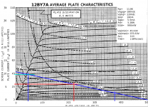
The 12BY7A is a real beast, having ratings more like a power pentode, as it was intended as a color TV video amp. As such, it likes high voltages (no shortage of that in a color TV) and the plate characteristics in the spec sheet are plotted against a screen voltage of 180Vdc, though it has a nice looking plate characteristic down around the -6.0V region (where this seems to be operating: Ip= 6.0mA). Dropping screen voltage and bias would keep the plate current the same, and get the screen voltage under the plate voltage where you want it.
6AU6's seem to be at their best with Ip= ~3.0mA, so may have been lacking a bit in the drive department, and perhaps y(f) too, despite working the 12BY7A at such a low plate current?
Stu didn't have access to the '99, with its high gm, back in the 1960s.
Sure he did, it was type number 5687....
FWIW, the Citation II also ran the 12BY7 with its g2 higher than its plates.
cheers,
Douglas
Could you briefly explain why?Eli Duttman said:That high gm provides resistance against slew limiting.
Could you briefly explain why?
Almost every text on hollow state tells you that tubes not driven into grid current require just voltage, not current. That isn't just an over simplification: it's just plain wrong. Even if Vgk never goes positive, the grid still had capacitance associated with it: Cgk + Cmiller + Cstray. The grid won't see the true signal level until that capacitance is fully charged, and it takes current to charge a capacitor. The faser you want that capacitor to charge, the more current you need to pump into it.
Take a look at this loadline. The driven stage will be demanding the most current when the 12BY7A is least able to supply it. When the plate voltage comes up, the potential difference across the plate resistor goes down. The ability to supply current to the load is:
I= (Vpp - Vplate) / Rp
That's why it's a good idea to make sure the Q-Point current is at least five times the peak current at the highest frequency of interest, and why the 12BY7A was designed in the first place: as a color TV video amp. Even though you try to make CRTs in such a manner to minimize internal capacitance, you can't completely eliminate it. Since you need to drive the cathodes of the color CRT at a max rate of 4MHz, it takes a pretty stiff current to charge that capacitance, even if it's held to picofarads.
If you use a tube with a high y(f) -- like the 12BY7A -- you can get the gain and the linearity with a much smaller plate load. The smaller plate load, the more current reserve.
This is something that gets overlooked a lot in audio designs. No way can something like a 12AX7 drive the grids of an audio power final, and keep up with the current demand. If there isn't enough current, the control grid(s) of the final(s) won't track the signal. That's the slew rate problem.
Attachments
No way can something like a 12AX7 drive the grids of an audio power final,
How about driving the grids of two KT88's in parallel? Yes, I wouldn't do it but Jadis did.
So Mullard were completely wrong to drive a LTP phase splitter with a pentode with such low gm and drive capability as an EF86, and then drive a pair of EL34s from this ECC83 splitter?
I accept that if you think you need a low anode load but still want high stage gain then a high gm valve is necessary. A low anode load may be necessary at this point if the LTP is biased into the grid current region - an easy way to do this is to run the LTP at too high a current (perhaps in order to 'drive' the output stage) or too low quiescent anode voltage. The design being considered here avoids that problem, fortunately. However, it has a large capacitor at the pentode anode (430pF) which creates the problem I thought we were trying to avoid. A 6CG7 LTP should not be particularly hard to drive so I am puzzled why such a low impedance input stage was chosen.
I accept that if you think you need a low anode load but still want high stage gain then a high gm valve is necessary. A low anode load may be necessary at this point if the LTP is biased into the grid current region - an easy way to do this is to run the LTP at too high a current (perhaps in order to 'drive' the output stage) or too low quiescent anode voltage. The design being considered here avoids that problem, fortunately. However, it has a large capacitor at the pentode anode (430pF) which creates the problem I thought we were trying to avoid. A 6CG7 LTP should not be particularly hard to drive so I am puzzled why such a low impedance input stage was chosen.
So Mullard were completely wrong to drive a LTP phase splitter with a pentode with such low gm and drive capability as an EF86, and then drive a pair of EL34s from this ECC83 splitter?
As far as I'm concerned, yes they were. That's not my design philosophy. When I used a 6SL7 for an LTP splitter, I installed cathode follower grid drivers between the low current triodes and the grids of the finals.
I accept that if you think you need a low anode load but still want high stage gain then a high gm valve is necessary. A low anode load may be necessary at this point if the LTP is biased into the grid current region - an easy way to do this is to run the LTP at too high a current (perhaps in order to 'drive' the output stage) or too low quiescent anode voltage. The design being considered here avoids that problem, fortunately. However, it has a large capacitor at the pentode anode (430pF) which creates the problem I thought we were trying to avoid. A 6CG7 LTP should not be particularly hard to drive so I am puzzled why such a low impedance input stage was chosen.
The problem with that Cit V design is that it uses an extremely high level of gNFB. That would explain the 12BY7A: needed to drive up the open loop gain to get that gNFB and maintain reasonable input sensitivity.
"However, it has a large capacitor at the pentode anode (430pF) which creates the problem I thought we were trying to avoid".
That 430pF capacitor is part of a Zobel paralleling the plate resistor. This is necessary to improve the phase margin at high frequencies so that you can run up the gNFB even more. Crowhurst's book, High Fidelity Design devotes four chapters to that very thing: phase corrections at both ends of the audio band for running up gNFB. That, too, just doesn't fit with my design philosophy, and excessive gNFB makes for a very solid statey sound. I don't need much more than 6db of gNFB, and 20db made a hollow state design sound as bad, if not worse, than any solid state design from the Big Box store.
An externally hosted image should be here but it was not working when we last tested it.
. Cutting that back to about 7db was right.Back in those days it was necessary since speaker design was a total "black art", and speeks designed back then had lots of squirrely impedance v. frequency misbehaviours that probably needed the extreme feedback to dampen that out.
Considering the designer was Stu Hegeman, you can be certain he had good reason. An obvious fact is the high gm of the 12BY7. That high gm provides resistance against slew limiting.
I find this unlikely. Three reasons:
1. To be perfectly pedantic, tubes rarely go into slew rate limiting per se, due to their relative linearity and the simplicity of circuitry they are found in. Slew rate limiting is a nonlinear (current saturation) phenomenon, typical of differential solid state amplifiers with current sources and mirrors. That said, larger tubes have lower output impedances (or drive lower impedance loads), achieving higher GBW, so the effect is similar, but it's the result of a linear process.
2. The 6CG7 is hardly a difficult load to drive. With Cin totaling under 100pF, this circuit is a good start for a wideband RF amplifier. Except that,
3. The designer rolled off high-frequency response intentionally with a pole-zero network across the 6CG7 grid.
The Cit. 5 employs Mullard style circuitry and a good deal of GNFB is present. Slew limiting is always a concern under those conditions.
I'm not sure what you mean by this. The goal of NFB, properly implemented, is to reduce gain, which reduces HF gain necessarily. The only condition that comes to mind where slew rate limiting would be a concern is a dead band in the output, such as a class C (unbiased) complementary emitter follower exhibits (similar circuits can be built from tubes, though they usually aren't, for obvious reasons).
The 6AV6 is a real pipsqueak with a Pd= 500mW.
Not that that's a concern; indeed, you're hard pressed to use a 12AX7 over 600mW (TubeLabs notwithstanding), and if you are, you're probably getting a lot of distortion too.
Not much drive capability there, and the 6CG7 LTP probably isn't gonna present a 6AV6 with a very friendly load.
The 1k + 430pF would have to be increased proportionally, but the drive capacity is more than sufficient for several octaves beyond the audible range.
The 12BY7A is a real beast, having ratings more like a power pentode, as it was intended as a color TV video amp. As such, it likes high voltages (no shortage of that in a color TV) and the plate characteristics in the spec sheet are plotted against a screen voltage of 180Vdc, though it has a nice looking plate characteristic down around the -6.0V region (where this seems to be operating: Ip= 6.0mA). Dropping screen voltage and bias would keep the plate current the same, and get the screen voltage under the plate voltage where you want it.
Yup, it's an excellent video / oscilloscope deflection amp. In fact, I have some Tektronix branded BY7's in my collection.
I'm partial to 7KY6 myself. They used to be bargain table items, not sure if they've gone up in recent years.
6AU6's seem to be at their best with Ip= ~3.0mA, so may have been lacking a bit in the drive department, and perhaps y(f) too, despite working the 12BY7A at such a low plate current?
I also have a bunch of Tektronix branded 6AU6s as well; they were no dummies, and they used them all over the place in amps over 10MHz. Just a matter of using them appropriately. They were also fond of 6DK6, which has twice the transconductance. Other FM / UHF radio tubes are also quite excellent, 6CB6 and so on.
So Mullard were completely wrong to drive a LTP phase splitter with a pentode with such low gm and drive capability as an EF86, and then drive a pair of EL34s from this ECC83 splitter?
If the result satisfies your design spec, then it sure as heck ain't wrong!
The wonderful thing about tube amps is, because they tend to be linear devices with simple R+C time constants, they are ridiculously easy to analyze, say through Laplace domain transfer functions (whereas solid state amps are best analyzed through brute force time domain SPICE simulations). Indeed, you can draw all the time constants and feedback elements in an amp, chug chug chug the equation, then solve for e.g. maximal bandwidth (+/- some dB), minimal overshoot, low output impedance, etc. And the result you get will be remarkably close. You're reducing your amp to a system of equations. Current and voltage are eliminated from the calculation, only time constants and frequency responses remain. If a section has insufficient frequency response (generally brought on by using a tube too small there), the associated term will stick out like a sore thumb. And if you actually perform this analysis... prepare to be surprised. People can create all sorts of strange rules, but equations don't lie!
Tim
The ability to slew well is measured in Volts per μ second. My slew limiting concern regarding GNFB lies with the HF error correction signal. A high gm device reacts more favorably to that signal. HF signals obviously entail greater voltage swings in the time domain.
"Bandersnatch" mentioned the 5687. I suspect Mr. Hegeman avoided it for its comparatively low μ and large heater draw. The nominal μ of the 5687 is 16, while that of the 6CG7 is 20 and that of the ECC99 is 22. Roughly 30% of μ will be the LTP's stage gain. The 6CG7 draws 600 mA. of heater current, the ECC99 draws 800 mA., and the 5687 draws 900 mA. FWIW, I asked Jim McShane if the Cit. 5 heater supply could take 2X ECC99s as replacements for 2X 6CG7s. Jim said it was safe to try. I don't know if it's safe to draw 200 additional mA., by installing 2X 5687s.
"Bandersnatch" mentioned the 5687. I suspect Mr. Hegeman avoided it for its comparatively low μ and large heater draw. The nominal μ of the 5687 is 16, while that of the 6CG7 is 20 and that of the ECC99 is 22. Roughly 30% of μ will be the LTP's stage gain. The 6CG7 draws 600 mA. of heater current, the ECC99 draws 800 mA., and the 5687 draws 900 mA. FWIW, I asked Jim McShane if the Cit. 5 heater supply could take 2X ECC99s as replacements for 2X 6CG7s. Jim said it was safe to try. I don't know if it's safe to draw 200 additional mA., by installing 2X 5687s.
Now I'm puzzled again!A high gm device reacts more favorably to that signal. HF signals obviously entail greater voltage swings in the time domain.
If you put a big lag in the forward signal path (e.g. most SS, the 430pF in this valve amp) in order to stabilise the loop then you create a need for higher slew rates in the circuit before the lag but we are still talking about audio signals (plus some distortion) so any valve will respond quickly enough. Circuit time constants easily swamp any valve response times. Video pentodes are designed to drive big capacitances, but the big capacitance here seems to be a consequence of the decision to use a video pentode rather than a driver of that decision.
Slightly off thread -
Someone above mentioned the Jadis, I've actually had an oscilloscope over the Jadis JA80 during one of many episodes of repairing the things after another blow up. The 2 KT88 grids in parallel have a single 510K Rg1 as the load on the wimpy 12AX7 driver. Any grid curent in a KT88 tube at all, causes the other KT88 of the pair to hog current till it melts.
The square wave at the grids is a very trapizoidal, that is it is severely slew rate limited in the forward path. The other thing you need to know to try to get your head around the Jadis is that the cathode feedback to the KT88 outputs is POSITIVE feedback and the circuit relies on the Ultralinear connection and the shunt feedback from the KT88 anodes to stabilize it.
All in all, the Jadis is probably the worst circuit design I've seen - don't copy it or its circuit techniques.
Cheers,
Ian
Last edited:
Someone above mentioned the Jadis
That was me. Funny thing - it sounds great.
Highly educational, scroll to bottom of page:
Audio Asylum Thread Printer
OK, this is likely going to be controversial and off topic. An homage to Allen Wright maybe - he liked its sound.
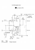
A little innovation. The ultimate UL driving stage is to connect a CCS to the screen of a 12BY7 (6CH6 shown here) which limits the screen about 5mA to a higher voltage feed than the anode supply is. Connect a high value cap from the screens to the anodes and the ideal U Linear stage is born. Many tubes succumb to this trick, example shows a wide b/w diff driver with also a CCS in the cathode which is voltage regulated and nicely balances out the F2 harmonic. This final bit forces a fixed cathode voltage for the diff cathode and linearises the tubes. It can be improved apon, but the layout requires attention with rising frequency. This stage gives excellent performance and I am currently using a similiar configuration in my amps. Those using such a stage will discover that mismatched tubes work fine and THD can be trimmed by altering one side of the CCS or swapping tubes; but the stage output drive voltage is far more than a simple RC stage and can accept substantial loading.
Those who have listened to power amps with such a circuit, claim a near mosfet performance, i.e bright, but beware this stage has an excellent slew rate and care is required with the amplifier design and perfect for a concertina and the ultimate output transformer.
Output Z is about 2K per side, fine for parallel push pull Miller dump.
Those who haven't noticed, the TV Video group of tubes are somewhat current hungry. A quick glance of the 12BY7 curves puts this tube optimally around the 12-20mA running mark, the design of the driver circuit requires a beefier power supply.
For those who may remark "why not put a CCS in the anode supply", the reason is that the anode resistor provides a damping impedance whereas a CCS doesn't and these TV Video driver tubes have a very high gm and a reputation to oscillate when given half the chance.
Note: Those wishing to patent such a circuit, beware; I have already reseached and published the design elsewhere.
richy
Attachments
A little innovation. The ultimate UL driving stage is to connect a CCS to the screen of a 12BY7 (6CH6 shown here) which limits the screen about 5mA to a higher voltage feed than the anode supply is. Connect a high value cap from the screens to the anodes and the ideal U Linear stage is born.
Neat trick to prevent screen poofage, but a UL it ain't. Given the impedances involved, a 1.0uF capacitor is enormous. That makes an AC coupled pseudotriode. UL implies some screen feedback, but not 100% screen feedback. Not sayin' it doesn't work, or that it's not a good idea, or that it doesn't have its uses, but it seems to be a bit of an overcomplication. If you simply connect the screen (with stopper) to the plate, you get the 100% screen feedback and solve the screen poofage problem all at once. If the plate and screen are always at the same potential, it won't poof. (Reference Tubelab's experiments with pseudotrioded 6AV5s and his screen voltage spec busting by huge margins.)
UL for a signal pent is usually done with a source follower driving the screen, with a portion of the output fed to its input via a voltage divider.
Output Z is about 2K per side, fine for parallel push pull Miller dump.
Zo is what I'd expect from a pseudotriode.
Those who haven't noticed, the TV Video group of tubes are somewhat current hungry. A quick glance of the 12BY7 curves puts this tube optimally around the 12-20mA running mark, the design of the driver circuit requires a beefier power supply.
Yep, I noticed. I also noticed that the plate characteristic becomes quite linear when you run a 12BY7A at below 10mA of plate current, like as was done here in this design. But that brings up the question of why do that in the first place? A 6AU6 (the 2N3904 of hollow state -- not sexy-schmexy exotic, just a reliable workhorse) is also really linear at about the same plate currents. So why use the beast, when you don't really need the plate current. Here, you're not slamming the input capacitance of a CRT four million times a second.
Was this a case of "standardizing" a design? Other Citation amps also used 12BY7As (as a preamp and an LTP splitter/voltage amp) where the drive capability was useful.
- Status
- This old topic is closed. If you want to reopen this topic, contact a moderator using the "Report Post" button.
- Home
- Amplifiers
- Tubes / Valves
- When can screen voltage be higher than plate???