Recently did a build of Frank's circuit, but modified it to run off the anodes as my power amp has in input impedance of 100k.
I'm using some 10uF mkp capacitors at the output (big I know, but it's all I had to hand), when I plugged it in, although the sound is great, there is noise - like a buzzing sound. I took out the caps and the buzzing is gone, but the gain is also gone - at full volume it's just the line level volume.
How can I begin troubleshooting the buzz/hum? It disappears without the caps, but why should the gain also disappear?
No worries - probably a smarter idea to give a schematic.
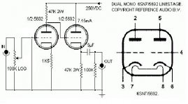
Schematic attached, however I've made some changes because I think when this line stage was designed it was to run the line pre into a SS power amp (hence need the cathode follower to give a low impedance output). But seeing as my power amp is 100k inoput impedance, I took out the cathode follower and now run the line pre as a plate follower (to lose any dreaded cathode follower effect). Plus it also meant I can take out one of the valves, so the load on the small power transformer is halved. I've wired the valves so that this can be quickly done (one valve shares the two plate followers, the other shares the two cathode followers).
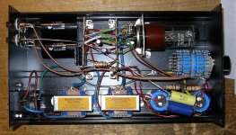
I've also put a picture of the build prior to removing one tube and modifying as follows (not sure how clear the wiring is in the pic):
(1) Removed the bottom tube from its socket.
(2) Removed the two (green) wires from the plates of the top valve going to the grids of the bottom valve.
(3) Removed the two 47k resistors going from the two output caps.
(4) De-soldered the (yellow) wires running from the two output caps to the bottom valve cathodes, and re-soldered them to the junction of the (blue) wires and the top valve plate 47k resistors.
After changing it I have noticed the following; (1) gain appears to be slightly higher, and (2) the buzz is exactly the same. Taking out the 10uF output caps removes all the gain, and the buzz - but I can't work out why this is the case. Clearly the aim is to have no buzz, but a decent amount of gain (theoretically it should be about 10x).
Schematic attached, however I've made some changes because I think when this line stage was designed it was to run the line pre into a SS power amp (hence need the cathode follower to give a low impedance output). But seeing as my power amp is 100k inoput impedance, I took out the cathode follower and now run the line pre as a plate follower (to lose any dreaded cathode follower effect). Plus it also meant I can take out one of the valves, so the load on the small power transformer is halved. I've wired the valves so that this can be quickly done (one valve shares the two plate followers, the other shares the two cathode followers).
I've also put a picture of the build prior to removing one tube and modifying as follows (not sure how clear the wiring is in the pic):
(1) Removed the bottom tube from its socket.
(2) Removed the two (green) wires from the plates of the top valve going to the grids of the bottom valve.
(3) Removed the two 47k resistors going from the two output caps.
(4) De-soldered the (yellow) wires running from the two output caps to the bottom valve cathodes, and re-soldered them to the junction of the (blue) wires and the top valve plate 47k resistors.
After changing it I have noticed the following; (1) gain appears to be slightly higher, and (2) the buzz is exactly the same. Taking out the 10uF output caps removes all the gain, and the buzz - but I can't work out why this is the case. Clearly the aim is to have no buzz, but a decent amount of gain (theoretically it should be about 10x).
Attachments
Ha - yes I thought so - unfortunately I don't have a scanner!
The power supply is PS is 220uf - 100R - 220uf - 100R - 220uf/1uf/0.47uf.
By the way, I can see why people have had so much success with Frank's Linestage - the purity of the sound is unrivaled in my experience (I've used half a dozen commercial and DIY preamps).
The only issue in my build is the noise - which seems to happen whether I use it as a cathode follower, or a plate/anode follower circuit. There is no noise without the output caps, but there is also no gain. Likewise, with the caps in place, the gain returns, as does the buzz/hum.
Well designed cathode followers have no effect, dreaded or otherwise, apart from buffering the signal.
From your description, it sounds like you have simply removed the CF - not converted the stage to a plate follower. You take output now directly from the anode of the first stage - this is a common cathode amplifer with cathode degeneration, not a plate follower. It will have high output impedance which means it will not ground any hum picked up on the interconnect. However, you say that removing the output coupling capacitor removes the hum (and signal too, of course!) so the hum is coming from the circuit rather than the interconnect.
The most likely cause of your problem is poor grounding. You are probably injecting charging pulses into your signal ground. I can see a bare ground wire arcing across the amp, but a picture does not give enough detail. What grounding scheme have you adopted - star, bus or some mixture? Exactly how are the negative ends of your smoothing caps grounded? Where does the ground wire attach to incoming signal ground and safety ground/chassis?
Sorry, clarification needed.
Removing output caps, you no longer have signal out to your amp. If you do have an attenuated signal out, it would mean your active stage is being bypassed and is a simple passive preamp...I can't see how that is by the pic.
Shorting the output caps will send full plate voltage to your amp.
Removing output caps, you no longer have signal out to your amp. If you do have an attenuated signal out, it would mean your active stage is being bypassed and is a simple passive preamp...I can't see how that is by the pic.
Shorting the output caps will send full plate voltage to your amp.
6BG6GA - what is your B+? What tube regulator? I have a ton of them just waiting for an opportunity...
Is it crazy to have SS rectifier with Tube rectification? I ask only because I have a single octal socket available if I go SS...would look cool with purple glow of a tube regulator...
Is it crazy to have SS rectifier with Tube rectification? I ask only because I have a single octal socket available if I go SS...would look cool with purple glow of a tube regulator...
Can we clarify something? When you say "remove the output cap" I assume you meant 'simply disconnect it', which would leave you with no noise and no signal. Others assume you meant 'replace it with a piece of wire', which would leave things virtually unchanged apart from the huge DC on the output. Which is right?
Can we clarify something? When you say "remove the output cap" I assume you meant 'simply disconnect it', which would leave you with no noise and no signal. Others assume you meant 'replace it with a piece of wire', which would leave things virtually unchanged apart from the huge DC on the output. Which is right?
Correct - replaced it with a piece of wire.
6BG6GA - what is your B+? What tube regulator? I have a ton of them just waiting for an opportunity...
Is it crazy to have SS rectifier with Tube rectification? I ask only because I have a single octal socket available if I go SS...would look cool with purple glow of a tube regulator...
I used 2) OD3's per channel. Dual power supply.
Is it crazy to have SS rectifier with Tube rectification? I ask only because I have a single octal socket available if I go SS...would look cool with purple glow of a tube regulator...
I used 2) OD3's per channel. Dual power supply.
lordearl: what you are doing is really quite crazy. You are removing a cap that is virtually guaranteed NOT to be the source of your problem, and as a consequence have ~ 250VDC on your interconnects. Now what happens if you handle the end of those interconnects while the preamp is turned on?
You have modified the design of an amp that worked pretty much correctly without understanding what you are doing, and in the process have made something that is pretty dangerous.
Look, I know its DIY here, and that we all probably take risks we shouldn't... but this is stupid.
Put the cap back in. Adapt some other known circuit using 1 tube that works with lower gain if thats what you want. Pay big attention to grounding, and use a ground breaker (back to back diodes, paralleled with a 10-30r >5W resistor and ~0.01uF cap, all with voltage ratings higher than your B+) to separate circuit ground from chassis (safety) earth.
(ps, you can always draw the circuit and take a photo using a phone/camera whatever).
I'm not trying to discourage you, but feel compelled to tell you what you have there is dangerous.
Fran
quote:
lordearl: what you are doing is really quite crazy. You are removing a cap that is virtually guaranteed NOT to be the source of your problem, and as a consequence have ~ 250VDC on your interconnects. Now what happens if you handle the end of those interconnects while the preamp is turned on?
He is absolutely correct. What your doing is dangerous. It can and will bite you in the ***. Installing a coupling cap/s in the amplifier isn't technically correct either. Set up the line stage the correct way. Doing so will eliminate the possibility of electric shock for you or someone else that happens to stumble across what you have done. Your not re-inventing the wheel here but you are creating a very dangerous and life threatening condition that could take your life or someone elses.
Change it now!!!
- Status
- This old topic is closed. If you want to reopen this topic, contact a moderator using the "Report Post" button.
- Home
- Amplifiers
- Tubes / Valves
- Frank's 6SN7 - plate follower, noise