Hello all,
I'm building an umbilical cable to connect my tube preamp power supply to the preamp chassis. I've done a lot of reading in this forum and others, and the general recommendation I have seen is to use a wire for the ground return between the two chassis, and a separate braided copper shield on the cable, connected to the chassis on the power supply end only.
However, in reading Morgan Jones' "Building Valve Amplifiers", I noticed that he said that the best way to ensure a low resistance connection between the two chassis was to use a heavy braided shield over the umbilical as both the shield and the ground connection. This implies that the shield is connected to both the power supply and the main preamp chassis. I know the Morgan Jones book is generally regarded as a "Bible" of sorts for valve circuits, so I'm a bit confused.
Is there a general rule of thumb on this subject? I'd love to hear from those in the know about what they prefer.
I'm very much on the side of MJ in this case. A braided shield, because of it's large cross section, will provide a nice low resistance ground connection betweem units. Grounding the shield at one end only refers much more to signal interconnects where the braid acts only as a shield and not a connecting conductor.
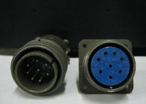
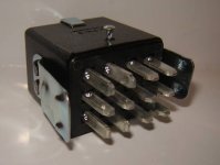
I'd also recommend using a quality (surplus) Amphenol, Bendix or Cannon "MS" type connector with a screw on collar. Cinch Jones locking connectors will also serve well. You know, the kind with rectangular flat pins. These will withstand the high voltages used.
I'd also recommend using a quality (surplus) Amphenol, Bendix or Cannon "MS" type connector with a screw on collar. Cinch Jones locking connectors will also serve well. You know, the kind with rectangular flat pins. These will withstand the high voltages used.
Attachments
Thanks, Hollowstate,
What about an 8-pole Speakon? I know that is frowned upon because of the possibility of mistakenly connecting a speaker to the power supply, but I have nothing else with a Speakon connection and I can't imagine anyone thinking it would be a good idea to connect a speaker to a preamp power supply. I like the easy disconnect and locking features of the Speakon - how bad is that idea?
What about an 8-pole Speakon? I know that is frowned upon because of the possibility of mistakenly connecting a speaker to the power supply, but I have nothing else with a Speakon connection and I can't imagine anyone thinking it would be a good idea to connect a speaker to a preamp power supply. I like the easy disconnect and locking features of the Speakon - how bad is that idea?
I'm unfamiliar with those connectors because I'm old school. So I looked them up to see what they were regarding voltage and current levels. If the specifications are correct, they should be suitable.What about an 8-pole Speakon?
Thanks. I'm planning to use some litz wire, braided shield and Techflex braid I have left from another project, so I really only need to buy the connectors. I love projects made from leftovers.
Any dissenting opinions about using the braid for the ground connection?
Using the shield of the umbilical for signal reference would be like using the chassis. It would prevent one from using a proper star ground scheme, where the signal reference connects to the chassis at a single point.
IMO and IME, the best way to do this is to route each power supply return (B+, heater, etc.) through the umbilical on a separate conductor and put the single point ground in the amplifier chassis. The power supply returns should connect to star ground AFTER the rectifier current loop, i.e. you don't want the filter cap charging current pulses on the return to star ground.
Litz wire for DC???
speakon cable connects necessitates multiple umbilicals/ multiple umbilicals = problems if u grounded every shield...
I have 7 wires and if I use an 8-pole speakon, I can make one umbilical to cover it all.
According to Morgan Jones, the ideal scheme would be to use all the shields together as both shields and earth conductors in such a situation. He even advocates using two or three layers of screening to ensure there are no gaps in the screens while also ensuring a low earth resistance.
This is a replacement umbilical for an existing preamp with separate power supply. The current umbilical consists of all 18ga solid core wires, run together and twisted into a spiral, without twisted pairs, carrying B+, ground return, 6.3V DC for signal tube heaters, 6V AC for regulator tube heaters, and DC for the remote. The is no hum problem with this arrangement but the solid wire is inflexible, the chassis connectors are kind of flimsy and I'm concerned about noise from the heater wires getting into the B+.
What I was planning to do originally is to twist together the B+ and ground, DC +/-, AC +/- and leave the remote power separate, then shield each of the three twisted pairs with copper braid, grounding at the PS end. After reading the MJ book, however, what I'm now thinking is to use the copper braid over the B+ as the ground return to ensure a robust earth ground connection and connect it at both the PS and preamp end, but keep the other two pairs as +/- wires inside a copper braid shield connected to ground at the PS end only.
Thoughts?
Last edited:
Might as well try it.
Not sure about using the B+/ground pair's shield as ground return. Maybe install a switch on the preamp end so you could try it both ways, easily.
I would probably also shield the remote power.
Maybe you could insulate the one with the shield used as ground return and then install another shield on top of that, grounded at PS end only (and then also insulate on top of that).
I would probably insulate each shield, and might try to fix an air gap between them all. (Not sure how, off the top of my head. Maybe glue them all to a piece of large-enough rope or flexible plastic tubing, spaced apart around the circumference? Then, ha ha, you could also shield and insulate the whole assembly.)
Or re-build the preamp to have distributed point-of-load power supplies... <grin>
Maybe this will help:
http://www.diyaudio.com/forums/diya...udio-component-grounding-interconnection.html
Last edited:
I am planning to insulate each of the shields from the others with teflon tape, then teflon tape those into one cable, then overwrap the whole thing with Techflex nylon braiding. That's the plan today, at least - it may evolve over the next few days as I wait for the speakons to arrive.
Maybe this will help: (See section 4.3)
http://www.diyaudio.com/forums/diya...ponent-grounding-interconnection.html?garpg=5
Remember to include the Safety Earth wire through your umbilical.
And it looks like you would want to connect an overall shield on both ends (to connect the two chassis together), but keep all of the +/- and +/gnd pairs separate from that.
If you're just substituting the use of a shield for the use of a wire for the B+/gnd cable, it shouldn't actually change anything, in a topological sense, especially if all of the other stuff in the umbilical is shielded (and insulated from it), and/or the shield used as ground is also insulated and single-end shielded.
Last edited:
I use speakons - 4 way for preamp HT and earth and 8 way for DHT filaments. I use a fixed connection and a 1 metre lead on the 4 way PSU side so it's fairly clear that this isn't meant for a speaker. On the amp side there's no power so if you did connect a speaker to the socket nothing would happen.
8 way speakons were used as an umbilical by Beard Audio. I believe they are rated at 300v but not sure if that's DC or AC.
andy
8 way speakons were used as an umbilical by Beard Audio. I believe they are rated at 300v but not sure if that's DC or AC.
andy
Maybe this will help: (See section 4.3)
http://www.diyaudio.com/forums/diya...ponent-grounding-interconnection.html?garpg=5
Remember to include the Safety Earth wire through your umbilical.
And it looks like you would want to connect an overall shield on both ends (to connect the two chassis together), but keep all of the +/- and +/gnd pairs separate from that.
If you're just substituting the use of a shield for the use of a wire for the B+/gnd cable, it shouldn't actually change anything, in a topological sense, especially if all of the other stuff in the umbilical is shielded (and insulated from it), and/or the shield used as ground is also insulated and single-end shielded.
Interesting reading. In its stock form, the umbilical has neither a separate safety ground wire nor a shield. The only grounding connection is between the star point of the PS and the star point (actually more like a buss) of the preamp, and each star point connector is screwed into its respective chassis.
Perhaps I should include a wire for the connection between the star points as in the stock configuration, twisted with the B+, and use the shield as the safety earth connection between the chassis - I'm thinking that's what Morgan Jones meant all along. If I do that, however, I then have both the ground wire and the shield connected to each chassis - isn't that a prescription for a ground loop issue? I'm thinking I'm probably better off replicating the scheme in the stock umbilical, just subbing the braided shield for the ground wire in order to minimize the resistance of the connection; I'd rather not redesign the entire grounding scheme, since I don't now have a problem with ground loops.
Last edited:
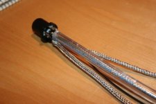
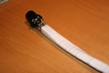
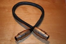
Well, here are pictures of the completed 1 meter umbilical in various stages of construction.
The B+ is coaxial with 1/4" braided copper shield which is also the ground return. It runs through the center of 1/4" ID Nalgene laboratory tubing which provides spacing away from the other wires, added safety insulation, and is very flexible. Wire for B+ is 11.5ga teflon insulated copper litz (gauge is large so that it fits snugly centered inside the coaxial braid).
The DC heater +/- and the AC heater +/- twisted pairs run outside the Nalgene tube and are each shielded with 1/4" copper braid. The braid is grounded to the chassis ground at the power supply end only. Wire is 15.5ga teflon insulated copper litz.
The remote control wire is unshielded and run outside the Nalgene tubing, 17.5ga teflon/copper litz.
The entire cable is wrapped in teflon tape, then in 3/4" nylon braid.
Connectors are Neutrik Speakon STX series. I used these because they have soldered connections rather than screw connections and can accomodate up to 10 gauge wire, so it was easy to solder the shield directly to the connector without using a drain wire. They are also touchproof and have a nice solid feel being made from die-cast metal. There is a plastic liner inside the metal shell to prevent any wires shorting to the shell.
Now I just need to drill holes for the Neutrik chassis connectors and hook them up.
Attachments
Last edited:
- Status
- This old topic is closed. If you want to reopen this topic, contact a moderator using the "Report Post" button.
- Home
- Amplifiers
- Tubes / Valves
- Preamp Umbilical - Use Shield as Ground Lead?