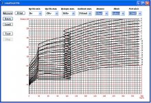
I"ve been playing with plots for various tubes since I got my "VACUUM TUBE ANALYZER" and find that the 6P43P has a strange plot compared to other similar tubes.
I've got screen captures of 6P14P, 6P15P, 6BQ5 and 6P43P in the word ".doc" file attachment.
Thinking it might be an oscillaton, I have installed a 0.001uf Cap from the grid to cathode, but it has little effect. Grid drive is via coax to shield it from surrounding circuitry.
I've attached the plot of the 6P43P-E and a zip of a word file with all plots.
Attachments
Hey,
Your vacuum tube analyser names itself as a "Lampemètre" ! That sounds French")
BTW, a common curiosity in all your captures is that the plate current MUST BE null when the plate voltage is.
What is this lampemètre ?
A simple test is to measure a simple resistor that must produce a tilted straight line crossing the origin: 0 Volts = 0 mA, and for, says a 10K one: 10ma at 100V, and so on as Mr Ohm told us
Yves.
Your vacuum tube analyser names itself as a "Lampemètre" ! That sounds French
BTW, a common curiosity in all your captures is that the plate current MUST BE null when the plate voltage is.
What is this lampemètre ?
A simple test is to measure a simple resistor that must produce a tilted straight line crossing the origin: 0 Volts = 0 mA, and for, says a 10K one: 10ma at 100V, and so on as Mr Ohm told us
Yves.
Good point on the resistor calibration Yvesm, and yes the test set is french.
The Lampemètre came from :
MODULE LAMPEMETRE ANALYSEUR - VACUUM TUBE ANALYZER - eBay.ch (endet 28.04.11 14:33:56 MESZ)
It is a nice little test set for the price, but the plate current starting above 0 is an issue with it, along with the fact that the cathode current, instead of anode current, is sensed via a 10R resistor which produces regenerative feedback and includes the G2 current as well.
I'm trying to figure out a way around those limitations, but for now I'm using the Lampemètre for initial testing.
I discussed about this problem with the seller Alain, who is possibly the designer as well. The conclusion is that I try to replace the 10 ohms current sensing resistor with 1 ohms and add the gain of the DC-amplifier by 10. Let's see if it works.
Oh yes, the screen current increases dramatically at low anode voltage and, since you measure in the cathode, here is the problem !
<edit to answer artosalo's message>
You are measuring the sum of the plate and the screen current, what could be the value of the sense resistor.
</edit>
If possible, try to return the negative terminal of the screen PSU to the cathode rather than to the ground so the screen current will no longer flow thru the 10R resistor.
Yves.
Last edited:
I will need to run a second ps for the G2 to be able to isolate it's supply return. I'll see what I can do about that. With low gG2 current requirements, it may be possible to install a filament transformer backwards to and run a voltage doubler to generate enough voltage for a grid supply.
I think some error is introduced as well by the zero Cross Detect used to start sampling data since AC is used for the anode supply and it is sampled to find the start point.
Artosalo, let me know if that works and I'll modify mine as well.
I think some error is introduced as well by the zero Cross Detect used to start sampling data since AC is used for the anode supply and it is sampled to find the start point.
Artosalo, let me know if that works and I'll modify mine as well.
Even the screen of a large (KT88) tube draws less than 10/20mA as long as the plate voltage is above 50 to 100 volts, below it sky rockets and may even blow the tube.I will need to run a second ps for the G2 to be able to isolate it's supply return. I'll see what I can do about that. With low gG2 current requirements, it may be possible to install a filament transformer backwards to and run a voltage doubler to generate enough voltage for a grid supply.
It's not a bad idea to use a weak PSU with a cap large enough to maintain voltage on peaks.
What voltage was the screen grid at? 120V?
G2 was 175V for the 6P43P-E and 250 for the others.
I used one leg of the B+ winding for the anode and the other for the G2 supply. Transformer is 250-0-250, and the G2 supply is regulated by a simple FET pass regulator with zener ref. It won't regulate above 350V because of sweep loading of the anode side.
"G2 was 175V for the 6P43P-E"
The screen current usually picks up strongly with plate V somewhere below the g2 voltage. Seeing as the g2 current is going thru the cathode sense resistor too, this looks to be the cause of the kinks (although the reduction of the plate V momentarily is odd, unless the g2 loading is feeding back thru the plate V supply). As Yvesm suggested, returning the g2 supply to the cathode directly should eliminate the plate current sense problem. Likely will have to use a separate xfmr for the g2 supply anyway, so the plate V feedthru will be fixed as well.
How many bits of resolution does the Lampemètre A/D converter have? Or maybe using a sound card interface?
Last edited:
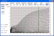
Another set of plots from last night (my computer at home won't boot so I have to wait till now to post).
I installed a transformer for g2 with the return taken from the cathode instead of ground so the screen current is no longer going through the cathode sense resistor.
The initial plots look much better but still off a good bit from the data sheet. The knee is still wrong. I had previously wondered if the PIC can keep up with the dv/dt of the ac waveform used for anode drive. In retrospect I would expect different distortion if that were the case.
With 60hz, 400Vpeak, the dv/dt is 6.6V/us at zero crossing. If the sample rate were too slow around zero cross, I would expect compression of the waveform with a steeper onset to the knee and that is not what is happening.
In the zip is one file that is really screwy. The 6P15P just went weird with alternating plots no matter what I did with the G2 voltage.
Right now the G2 transformer is on the bench. I need to find one with a higher output voltage to mount inside.
Next up will be changing the cathode resistor from 10R to 1R to minimize cathode feedback, and increase the gain of the op amp ckt to compensate.
Attachments
Last edited:
You could try attenuating the plate voltage further to see if dV/dt is a problem. Is there a sample and hold before the comparator? I would think that a tracking D/A and comparator would have some accuracy problems with fast slewing waveforms without a sample and hold. I think Analog Devices makes such a S/H chip. If the digitized waveform is not stable, then I would check for some HF oscillation of the tube. If so, some grid stoppers and ferrite beads are in order.
It appears that the distortion is still related to screen current in some way. The screen supply needs to have low capacitance to ground since it is floating on the cathode current sense resistor.
It appears that the distortion is still related to screen current in some way. The screen supply needs to have low capacitance to ground since it is floating on the cathode current sense resistor.
Last edited:
Mmmmh . . .
In my first attempt I envisged to use a PIC for A to D conversion but I was unable to sample current and voltage simultaneously (well, almost ...) even using the sample and hold properties and counting machine cycles.
This may explain that ?
Then, I went to a stereo sound board . . .
6P15 has no internal connection btwn K and G3 I know, I've paid
In my first attempt I envisged to use a PIC for A to D conversion but I was unable to sample current and voltage simultaneously (well, almost ...) even using the sample and hold properties and counting machine cycles.
This may explain that ?
Then, I went to a stereo sound board . . .
6P15 has no internal connection btwn K and G3
I know, I've paid The software algorithm used to do the A/D conversion can in fast slew cases be speeded up (provided there is a sample and hold feature) by using the logarithmic successive approximation technique. This homes in on the solution from most significant bit down to least sig. bit, bitwise. But requires 10 iterations thru the loop for 10 bits.
The other simple approach of using an up/down counter for the D/A is rather slower for random signals, but works quite well for smoothly slewing waveforms, up till the loop's max slew rate is reached. Only one iteration thru the software loop needed at the max slew rate of one count per sample. It is possible to combine the two approaches in a hybrid scheme for waveform tracking, that jumps the count ahead or back by 1/2/4/2/1 counts etc, ie, then back or forward 1 or 2 counts, then +/- 1 count to home in on the signal.
Even so, there really need be no issue with A/D speed for this application at all. You just need a memory table to integrate all the point measurements together over several sweeps (or use multiple pointers for the moving sample points on each stepped waveform). (a S/H is required though still ) Going this slow route can also enable averaging over multiple sample sets to remove noise, but too many data sets accumulated could lead to tube heating/drift problems.
UhOh...., I just realized that if there is only ONE S/H, then there is a timing issue between the voltage and current digitizations. One would need to add two outboard S/H units to synchronize them, or revert to the slow scanning scheme above with voltage digitizations and current digitizations on alternate sweeps, but this would require perfect identical software timing in each pass. The software would have to be designed to consume the same number of clock cycles on all software branches. Whew.. tough to code.
Last edited:
At first I thought I had an oscillation problem with a 6P43P-e so I added ferrite beads on the grid, G2 and Plate at the tube socket. I also added a cap from grid to cathode per the manual on the tube test set.
The manual on the PIC shows a s/h with a tau of .42us maximum. The a/d converter takes 10 cycles to convert, so it is either ratiometric or SAR.
I just realized that since the input waveform is scaled before feeding the a/d, the dv/dt at the converter should be much less, probably around .00155v/us so compared to the s/h time constant the dv/dt of the anode voltage should not be an issue.
Back to scratching my head.
I may try attenuating the plate voltage any way just to see what happens. Plat supply is now seperate from all other power supplies so I can put a variac on it and dial it down.
Last edited:
I am working on a 8051 design which does not use AC on the anode. Rather it will use a DC supply with the voltage controlled by a d/a. This way I am not time constrained (other than by dissipation of tube structures). I can step the voltage, let it settle, take a reading, proceed to the next step...Mmmmh . . .
In my first attempt I envisged to use a PIC for A to D conversion but I was unable to sample current and voltage simultaneously (well, almost ...) even using the sample and hold properties and counting machine cycles.
This may explain that ?
Then, I went to a stereo sound board . . .
I was actually more concerned with d/a conversion time for control since I was using a serial d/a. It ended being too long so I switched to a parallel d/a and can now do four a/d conversions and one d/a cycle in 116us (c code, not assembly). This should translate to near 16 sweeps per second from 0 to 500v in 1V increments if my HV Sweep control amp is fast enough (next part to prototype).
6P15 has no internal connection btwn K and G3
Yes, I made a jumper just for this.
What happens without the connection? Fried G3? Does this happen even with quick sweeps in a curve tracer?
Last edited:
Leaving g3 disconnected will in most cases cause it to charge negative, and so lower plate current some. But g3 is not very effective in most normal tubes (other than mixer tubes), so just a slight reduction in plate current, mainly at low plate voltage. Try it and see.
Ran out of time editing my last post:
The timing issue, with only one S/H on the chip, could also be handled by using a real time clock to accurately time the sample conversions on altenating scans for plate voltage and for plate current. Assumes the line voltage is steady.
You might also try another tube, could be defective! A gassy tube would have abnormally low plate current at low plate voltage. Excessive screen grid current could be a tip-off that the tube is gassy.
Last edited:
Another dissadvantage of of using AC on the plate is the non-linear dv/dt which requires a one to sample at a time varying rate in order to linearize the sweep.
One way to help is to use a voltage higher than the sweep requirement and ignore portion near peak as it changes slowly. This however worstens the voltage near zero as it makes dv/dt greater. The voltage near zero crossing is more difficult and requires fast processing to get enough data. Unfortunatly this is where multi-grid tubes have the most interesting data and requires close sampling, say 1V between samples.
One way to help is to use a voltage higher than the sweep requirement and ignore portion near peak as it changes slowly. This however worstens the voltage near zero as it makes dv/dt greater. The voltage near zero crossing is more difficult and requires fast processing to get enough data. Unfortunatly this is where multi-grid tubes have the most interesting data and requires close sampling, say 1V between samples.
The AC sine wave sweep can be useful. It keeps the tube out of the g2 major heating region most of the time (at least for an analog tracer). But a single sweep session using digitization avoids the problem nicely.
One thing I noticed on the traces so far is that the max plate voltage is the same for each stepped trace. Usually a current limiting resistor gets put in series with the plate to limit max dissipation. Unless maybe the software is post selecting the data points. This max dissipation issue is one area where I could see using a driven plate supply and software calculating the max dissipation for each sweep.
Also very useful is an adjustable current limit on the g2 supply.
I have some Xantrex bench supplies here that have 16 bit RS-232 controls and readbacks, which I have thought of using for a programmable tracer, with Visual Basic controlling everything. Since I got the Tek 576 tracer working though, I haven't had much impetus to work on that. But for Spice tube modeling, the digitization would be essential. Another scheme is to make the curve tracer become the real time tube Spice model itself, useful for variable g2 signals and current measurements. Probably need to have the tracer software do some predictive sampling and software interpolation to stay ahead of the Spice simulation, for speed.
Last edited:
- Status
- This old topic is closed. If you want to reopen this topic, contact a moderator using the "Report Post" button.
- Home
- Amplifiers
- Tubes / Valves
- 6P43P Strange Plate Graphs