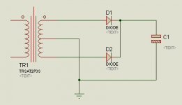
Hey, I have the following transformer being used in a system that I am making.
My power supply needs:
250VAC (from one end of the HV to the Center Tap)
6.3VAC (from the far ends of the heater winding)
12VAC (from a separate, non-CT transformer)
Do I need to ground the center tap of the 6.3V winding?
Do I snip off the other HV wire and cover the end?
How can I use a 12VAC transformer with no center tap in this circuit?
Question marks indicate the questionable connections.
Thank you.
An externally hosted image should be here but it was not working when we last tested it.
My power supply needs:
250VAC (from one end of the HV to the Center Tap)
6.3VAC (from the far ends of the heater winding)
12VAC (from a separate, non-CT transformer)
Do I need to ground the center tap of the 6.3V winding?
Do I snip off the other HV wire and cover the end?
How can I use a 12VAC transformer with no center tap in this circuit?
Question marks indicate the questionable connections.
An externally hosted image should be here but it was not working when we last tested it.
Thank you.
Hi.
With a non center tapped transformer like your 12 volt, you use the bridge rectifier. (four diodes) The AC goes into the top corners of the diamond. the DC comes out the other two. no center tap needed. When making a full wave rectifier with just two diodes, that is when you need the center tap. The anode of one diode goes to each end of the transformers secondary, The cathodes are tied together. that is the positive output of the rectifier. the negative end comes from the center tap. The bridge will give you a peak dc voltage of 1.4 times the transformers secondary minus 2 diode drops. For a fullwave rectifier with the center tapped transformer you get 1.4 times the secondary voltage across both legs of the transformer minus one diode drop.
As for the high voltage if you are using a bridge and don't need the center tap, you should have either a 250 volt non center tapped transformer, or a 125-0 125 and just ignore the tap. don't cut it. you might want to reuse it somewhere else someday.
read up on basic power supply design. lots of info on the web.
Cheers.
Rolf.
You would normally ground the CT of the HV supply and use a dual rectifier tube or 2 silicon diodes.

You can do the same with the 6.3V it will still leave you enough headroom (8.9V) to regulate down.
You can't use a single secondary 12V tx to get +- 15, you will need a CT or dual secondary. You'll only get +-17VDC so although this will work with LDO regulators, you're cutting it a bit fine with 78xx, 79xx series which have 2V dropout voltage, and you have to think about supply voltage fluctuation even with LDO.
w
- Status
- This old topic is closed. If you want to reopen this topic, contact a moderator using the "Report Post" button.
- Home
- Amplifiers
- Tubes / Valves
- Transformer wiring (Need Help)