First, let me say that this is a test and measurement question. I doubt that there is anything very wrong with the amp under test.
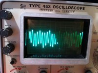
I'm working on an EL-34 push pull amp and I am getting this waveform at the coupling cap between the phase splitter and the EL-34 grids. I'm using a B&K signal generator and a Tek scope. The chassis is grounded to the house ground. I get just the slightest hint of this dancing wave form at the RCA input jack when I use an ungrounded probe. When I attach the ground to the probe and the RCA (-) the wave form lines out. Following the signal path through the amp the wave form gets worse until it's like you see below at the grid of the power tube (It's dancing all over the place). But, attached to the speaker terminals the wave form looks just fine again.
Just about any place in the signal path between the first plate and the transformer primary, I get this strange wave form.
I have dozens of theories, but nothing that will really stand up to scrutiny. It's a vintage Fisher power amp with older electrolytics and the B+ wave form has a pretty good saw to it and I wonder if the wave form isn't just following that rise and fall.
Any explanations or thoughts would be greatly appreciated.
CD
Attachments
Last edited:
Your getting mains hum modulating your signal.
Earthing problem.
Thanks for the help. Are you saying its an earthing problem on my bench - between the amp, signal generator and scope - or is it a problem within the amp?
I've not had this problem with other equipment under test.
Thanks for the help. Are you saying its an earthing problem on my bench - between the amp, signal generator and scope - or is it a problem within the amp?
I've not had this problem with other equipment under test.
First try the amp without an earth to zero volts.
If that doesnt fix it try it with an earth.
A lot depends on what equipment you have connected as to whether the earth is required or not.
Multiple earth paths will cause hum.
Some amps have an earth lift switch to cope with this problem.
Whatever you do dont remove the earth from the chassis.
This is a vintage amp with a two prong cord so it doesn't have a chassis earth. I used a clip lead at my bench to ground the chassis. I got this wave form with and without the ground lead connected to the chassis.
What I did not try was reversing the polarity of the AC cord at the socket.
What I did not try was reversing the polarity of the AC cord at the socket.
You definately have a grounding problem ...
http://www.el34world.com/charts/grounds.htm
Regards, Peter
http://www.el34world.com/charts/grounds.htm
Regards, Peter
Do these have the 3-prong power plugs? Are the power plug grounds connected to the signal grounds of the B&K output and the scope input? (use a DMM and look for a couple ohms or less resistance.) If they're not connected it may not be "wrong" - much equipment (especially power supplies) have separate "power plug" ground connections that can be connected or disconnected from the signal ground.First, let me say that this is a test and measurement question. I doubt that there is anything very wrong with the amp under test.
I'm working on an EL-34 push pull amp and I am getting this waveform at the coupling cap between the phase splitter and the EL-34 grids. I'm using a B&K signal generator and a Tek scope.
What is the scope sweep rate? What are the components we're seeing? As someone said, it looks like a sine wave riding on a sawtooth wave. Which is the signal generator, and what frequency is is outputting?
I suspect it's related to the high impedance in the tube grid circuits (including the high value resistor in the driving tube's plate circuit) that more readily pick up stray hum when the probe is connected.. The amplifier input is low impedance because you're actually looking at the low output impedance of the signal generator, and it won't pick up much hum with that connected.
The signal generator and the scope both have 3 prong plugs. The amp does not, but I use a ground strap to the chassis at the bench. The photo was taken at 210hz with a sweep rate of 10ms. The wave form was as depicted with or without the ground strap attached to the chassis.
I measured the resistance between the ground strap and the scope probe alligator clip at .3R and the ground strap to signal generator negative at .7R.
I have not mentioned it, but the amp is a Fisher 300. I have looked carefully for grounding issues and have not seen anything.
If you look carefully you can see that 7 cycles takes it through two of the longer waves. 210/3.5=60. It does look like a 210 hz signal riding on a 60hz wave form. The scale is 1 volt per cm. The ground plug is clean when scoped.
Last edited:
Up your test frequency by a factor of 10, and look to see if the modulation is sinusoidal or sawtooth. If sawtooth it is power supply ripple induced. If sinusoidal it is mains interfierence. Also check the frequency and if line frequency that is where it is comming from, if 2X line frequency then it is power supply induced.
Looks like HT ripple. This will largely cancel in the output stage, as the ripple will be applied in phase while the signal will be antiphase. It could be a sign that HT caps need replacing, or it could be normal for this amp.
I'd bet on this one...
It is caused by the effect of negative feedback trying to cancel out some hum somewhere.
To cure this you need to disconnect the feedback loop.
You will find the gain goes up a lot and hum appears at the output.
Now you have a chance to improve matters.
It could be that the amp is working correctly in which case the neg fb is doing what it's supposed to....
Regards
Henry
To cure this you need to disconnect the feedback loop.
You will find the gain goes up a lot and hum appears at the output.
Now you have a chance to improve matters.
It could be that the amp is working correctly in which case the neg fb is doing what it's supposed to....
Regards
Henry
- Status
- This old topic is closed. If you want to reopen this topic, contact a moderator using the "Report Post" button.
- Home
- Amplifiers
- Tubes / Valves
- What is up with this wave form?