Hi there,
This is my first post and I'm afraid its about a chinese amp (sorry - I know its a DIY forum). I have owned this amp for around 4 years and have generally been quite impressed with the sound. I'm looking in to building a tubelab Simple SE, but I would like to know that I can resolve the issues with this amplifier before I go down that road!
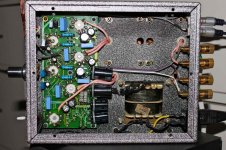
The amp has a small amount of hum in the left channel - which I believe may be able to be tweaked using one of the pots fitted across the 6N1 tubes (middle two pots in first photo). Any ideas if this is correct? I've fitted an earth tab to the chassis as recommended on here for safety which didn't help with the hum.
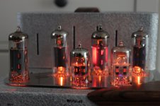
The other problem is that the plate on the third 6p1 from the left glows brightly during use (see second photo). Swapped tubes and the problem doesn't move and have also tried a set of 6P1P-EV tubes which do the same thing. I've measured the heater voltage which looks ok (6V AC). I was expecting it to be a bit on the high side as I've read that these amps are actually designed for 220V (I'm in the UK so the voltage is ~240V). Could adjusting the other two pots help with this problem or is there a fixed resistor which is at fault? There are no components that are obviously faulty.
Thanks for your help.
Toby
This is my first post and I'm afraid its about a chinese amp (sorry - I know its a DIY forum). I have owned this amp for around 4 years and have generally been quite impressed with the sound. I'm looking in to building a tubelab Simple SE, but I would like to know that I can resolve the issues with this amplifier before I go down that road!
The amp has a small amount of hum in the left channel - which I believe may be able to be tweaked using one of the pots fitted across the 6N1 tubes (middle two pots in first photo). Any ideas if this is correct? I've fitted an earth tab to the chassis as recommended on here for safety which didn't help with the hum.
The other problem is that the plate on the third 6p1 from the left glows brightly during use (see second photo). Swapped tubes and the problem doesn't move and have also tried a set of 6P1P-EV tubes which do the same thing. I've measured the heater voltage which looks ok (6V AC). I was expecting it to be a bit on the high side as I've read that these amps are actually designed for 220V (I'm in the UK so the voltage is ~240V). Could adjusting the other two pots help with this problem or is there a fixed resistor which is at fault? There are no components that are obviously faulty.
Thanks for your help.
Toby
Attachments
Hi,
Unless you are already know how tube circuits work ,I do not
advise that you adjust those pots.If you know the pinouts of the tubes
used in the amp then you can make a better idea of what they do in the
circuits.Try to get a schematic of the amp it will be easier.
Unless it is stated for international use it is best to assume this amp
was designed for china domestic AC voltage of 220Vac.Therefore you can
bet that the amp is at least 10% increase in operating voltage and current.
In general the design is already pushing the operating limits of the tubes
so at your UK voltage if you are lucky may have reached near maximum
tube limits.Seeing that you have operated this amp for four years it is most
likely to be the case.The 6P1 that you see glowing could be the result of
tube aging where it's internal resistance may have changed so that it is
running near maximum and it will likely fail before the rest of the 6P1s.
An easy solution would be to use a variac and adjust the input AC voltage
back to 220Vac. that way it is back to designed condition.Another solution is
to use high power resistors about 20W to drop the anode voltage to it's
original design if you know what that is (300Vdc?) or you can make a guess by looking at it's operating curves datasheet which you can find to download.
It is also advisable to measure the cathode current of 6P1 across the cathode resistor to get an idea of where 6P1 is operating at.So you can calculate how much power it is dissipating in relation to it's stated maximum.
singa
Hi Singa,
Thanks for your reply.
I'll try and locate a schematic for the amp. I have seen some on this site, but I understand that there may be a number of different versions (some using EL84).
Using a variac sounds like a good idea, only thing is that the heater voltage is a little low at 6.3V (actually, I'm not sure if this is an operating voltage or maximum). Would a high power resistor be used on the input to the amp (in which case the heater voltage would drop further)?
I'm not that the glowing plate is caused by tube ageing (not to say that the tubes have not suffered during operation!) because the problem remains when the tubes are swapped.
I will try and measure the cathode current later on today.
Cheers,
Toby
could you post a schematic that came with your amp? That is definitely a problem there. The "red-plating" tube means the tube is running above its maximum dissipation.
Being a tube it can probably take that beating for a short while but it's life will be greatly diminished. Check the voltage across the plate and cathode and multiply with the current running through the tube. Usually there is a sense cathode resistor that you can measure the voltage across.
The product of the Anode-Cathode voltage multiplied with the current will give you the dissipation, which should not exceed 12W for the 6P1. If the current is way off, I suspect the biasing may have shifted and you will probably need to rebias.
@singa, I do not think this is a tube aging problem as he has swapped his tubes around and even used another set of 6P1P-ev... and all have the same problem. I suspect the bias circuitry may be problematic.
Last edited:
Toby.
This won't help fix your existing amp.
But if you fancy having a play......
I have a spare complete pcb for the 6p14 version of this amp, which i tried to sell but failed. You are welcome to it.
My guess is that the transformers are all the same, so it could be a straight swap, if you can figure out the output TX connections. Shouldn't be too hard.
I ran mine at reduced voltage, but the heater voltages were still all over the place if i remember correctly.
Whilst it sounded ok, i decided to build a DIYparadise Simple el84 using the output transformers from the Aria. Which turned out to be quite good.
The new amp is much nicer in my opinion.
The Aria chassis now houses a little Tripath amp.
Nothing much wasted.")
I never managed to find a schematic for mine. There were several posted on the web, but not the right one. You need to search for a diagram in some of the older threads, without this you may struggle.
I'm not sure if any two of these amps were actually built the same.
Just a thought....
Given that these amps run quite hot anyway it might worth checking all the solder joints for a bad one. Doesn't cost anything.
This won't help fix your existing amp.
But if you fancy having a play......
I have a spare complete pcb for the 6p14 version of this amp, which i tried to sell but failed. You are welcome to it.
My guess is that the transformers are all the same, so it could be a straight swap, if you can figure out the output TX connections. Shouldn't be too hard.
I ran mine at reduced voltage, but the heater voltages were still all over the place if i remember correctly.
Whilst it sounded ok, i decided to build a DIYparadise Simple el84 using the output transformers from the Aria. Which turned out to be quite good.
The new amp is much nicer in my opinion.
The Aria chassis now houses a little Tripath amp.
Nothing much wasted.
I never managed to find a schematic for mine. There were several posted on the web, but not the right one. You need to search for a diagram in some of the older threads, without this you may struggle.
I'm not sure if any two of these amps were actually built the same.
Just a thought....
Given that these amps run quite hot anyway it might worth checking all the solder joints for a bad one. Doesn't cost anything.
Last edited:
The other problem is that the plate on the third 6p1 from the left glows brightly during use (see second photo). Swapped tubes and the problem doesn't move and have also tried a set of 6P1P-EV tubes which do the same thing.
In a situation like that, suspect a leaky coupling capacitor, or a cold joint that's worked loose.
@quikie22
I've found a schematic for the Meng 6P1 (see post 2), although I'm not sure how accurate it is yet:
www.diyaudio.com/forums/tubes-valves/157134-meng-yue-mini-schematic.html
I measured the following across the upper two 6P1s in the photo:
Upper Valve
Voltage across anode and cathode (pin 1 & 3): 256V
Anode current (meter between pin 1 and transformer wire desoldered from pin1): 40mA
Dissipation: 10.2W
Lower Valve (with the glow)
Voltage across anode and cathode (pin 1 & 3): 253V
Anode current (meter between pin 1 and transformer wire desoldered from pin1): 136mA
Dissipation: 34.4W
So the current and therefore dissipation is two high on that tube (if I'm measuring correctly).
@Trebla
Thanks very much for the offer, thats very kind. I'll find out about the transformers and may well take you up on that!
Couldn't see any dry joints on either side, but I'll check again.
These amps use cathode bias. I would suspect a dead (shorted) cathode bypass capacitor or a blob of solder in the wrong place on the PCB. The grid coupling caps in these are actually quite good (Class X2 MKP), and appropriately rated. The cathode bypass caps are only 25v rated from memory, and I have seen close to 25v DC in these amps with the thermal runaway that often accompanies running them on 240v. Normal cathode voltage is around 10-12v.
Check out the Mengyue Mini schematic thread on here where we solved a number of problems with these amps and the end result was very nice indeed.
Gary
Check out the Mengyue Mini schematic thread on here where we solved a number of problems with these amps and the end result was very nice indeed.
Gary
Ground pin 7 on the bad socket as a test. If the tube cools down its a bad connection/component going towards the grid. (i.e. the stopper, the leak resistor or the coupling cap.
Or just check the voltage on pin 7. If it's positive its that group of suspects. Otherwise it's the cathode cap or resistor shorted.
Or just check the voltage on pin 7. If it's positive its that group of suspects. Otherwise it's the cathode cap or resistor shorted.
Upper Valve
Voltage across anode and cathode (pin 1 & 3): 256V
Anode current (meter between pin 1 and transformer wire desoldered from pin1): 40mA
Dissipation: 10.2W
Lower Valve (with the glow)
Voltage across anode and cathode (pin 1 & 3): 253V
Anode current (meter between pin 1 and transformer wire desoldered from pin1): 136mA
Dissipation: 34.4W
Hi,Good work but all you need to measure current and dissipation is just
measure voltage across cathode resistor and divide by this resistor will give
tube's bias current without breaking open the circuit.So there is definitely
something wrong in cathode section as the voltage from anode to cathode is similar. singa
Ps from the schematic try adjusting the bias pot of the driver tube 6N2 if you can make it the same with the good channel?
Last edited:
Hi Gary,
I measured across the cathode bypass capacitor from each 6P1 of the left channel. The cap from the glowing tube measured short (the other one was 360ohms which is correct) and removed the cap and measured again. You were spot on, the cap had failed (shorted)! I replaced it with a 220uF rated at 35V (couldn't get hold of a 330uF which was fitted originally).
There is no tube glow and the hum has greatly reduced on the left channel (although there is still a small amount from each speaker). I plan to check the current again on each tube and perhaps modify the design if they are too high.
Thanks to everyone who posted, you have been most helpful! I'm starting to get some appreciation of how valve amplifiers work and how to check for and resolve problems.
Cheers,
Toby
You could try, then let us know ;-)
But I am sure the Russian GU-50 can do that. I have literallly red-plated those guys to glory (shorted cathode resistor) and still they function like normal.
IIRC the tagline from a Maplin MOSFET amp, "So tough it can rival the toughest tube amps" or something like that. Journalistic license or not, it was one of my few amps that survived a short circuit for several months duration without burning up. (We had moved and my wife had wrongly connected the wires and had connected output direct to ground). I discovered it when I was listening to my fave CD and noticed that it did not sound right, and tried looking behind the amp...
Anyway, it does show that tube amps were the the "gold standard" when it came to toughness that everything else was compared to them.
- Status
- This old topic is closed. If you want to reopen this topic, contact a moderator using the "Report Post" button.
- Home
- Amplifiers
- Tubes / Valves
- Problem with Aria (Meng) Mini 6p1 (glowing plate)