Cathode feedback windings are NOT new. Whatever patent Amplimo holds is not on that concept.
Amplimo and Plitron (Canada) are "joined at the hip". Plitron builds Vanderveen designed toroidal trafos. Descriptions of Plitron's tube O/P trafos, including those with CFB windings, can be found here
Amplimo and Plitron (Canada) are "joined at the hip". Plitron builds Vanderveen designed toroidal trafos. Descriptions of Plitron's tube O/P trafos, including those with CFB windings, can be found here
Its really not new, I have seen cathode feedback design in Russian magazine published back in 1958.
Vintage amps like Sansui AU-111 and Quad II are examples of cathode feedback. McIntosh unity coupled is actually a 50% cathode feedback (invented in 1936).
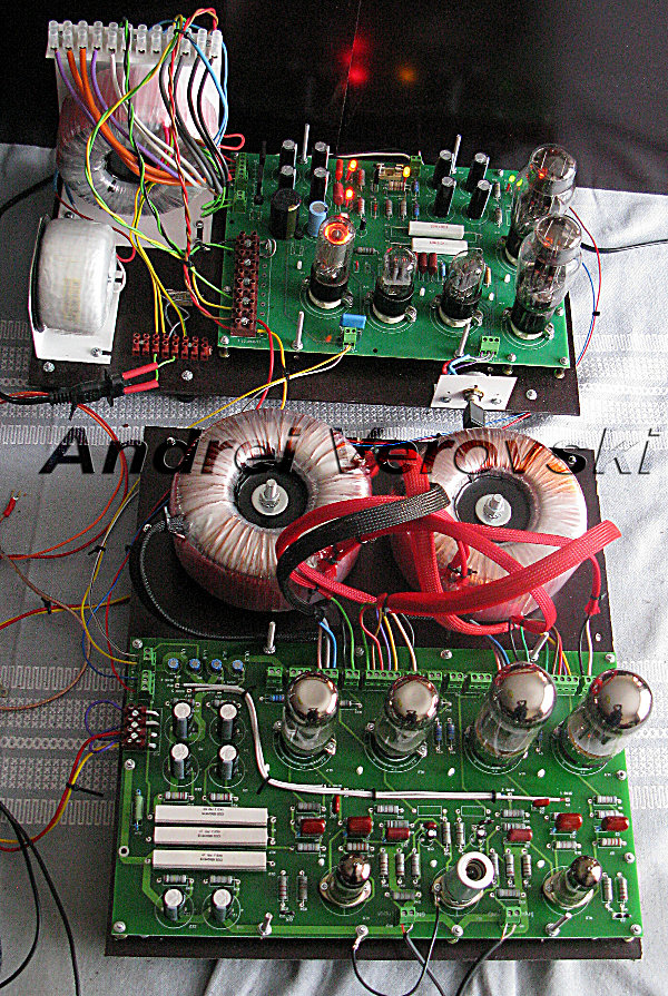
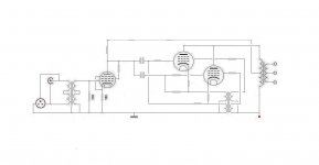
Below you can see draft assembly of PP amp with CFB trafos of my own design
Vintage amps like Sansui AU-111 and Quad II are examples of cathode feedback. McIntosh unity coupled is actually a 50% cathode feedback (invented in 1936).
Below you can see draft assembly of PP amp with CFB trafos of my own design
hmm, maybe anode phase splitter choke for driver tube
and 'added' trafo for cathode and garter bias
due to current, sutrely not an interstage
but how about a toroid power trafo
not a CT, but double symmetric windings
though all primary, wouldnt they also work ok as 2x primary and 2x secondary
and 'added' trafo for cathode and garter bias
due to current, sutrely not an interstage
but how about a toroid power trafo
not a CT, but double symmetric windings
though all primary, wouldnt they also work ok as 2x primary and 2x secondary
interesting Crowhurst amp
original DIY 'kit' from 1957-1960
curcuit and setup explained in detail
http://www.audioxpress.com/magsdirx/ax/addenda/media/1960crowhurst.pdf
original DIY 'kit' from 1957-1960
curcuit and setup explained in detail
http://www.audioxpress.com/magsdirx/ax/addenda/media/1960crowhurst.pdf
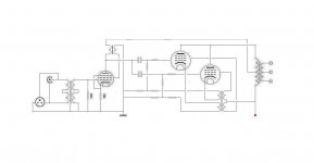
The schematic in post #7....
hey, I think I made some mistakes from looking at pushpull CFB designs,
and this is SE
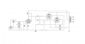
just for the record, the corrected version
like you, I also have my doubts, ofcourse
well, for one, it needs to be a high current trafo
maybe a 'cheap' custom trafo could do it
Attachments

If cathode feedback is implemented, and the screen is referenced to ground, then this also implies a measure of ultralinear (screen feedback). To prevent that, the screen should be referenced to the cathode by using a floating power supply, or, there should be an UL tap with teh same percentage feedback as the CFB, but 'crossed' between the screens so that it cancels out CFB. Looking tat that arrangement ot first glance it may appear as positive feedback to the screen grids.
"the screen should be referenced to the cathode by using a floating power supply, or, there should be an UL tap with teh same percentage feedback as the CFB, but 'crossed' between the screens so that it cancels out CFB"
I think thats what Tinitus is doing with the lower windings shown now. (needs some phase dots on the windings) (and the two winding sets shown at bottom are in parallel so they could be combined into one)
My earlier comment about pos. fdbk on the screen was referring to the V1 input tube screen connection in post #7. The latest version now looks like the so called "E-linear" connection for V1, which is fine. "Schade" style neg. feedback. Maybe a bit of overkill on the Neg. fdbk unless the CFB% is low (like use the secondary winding for CFB).
Last edited:
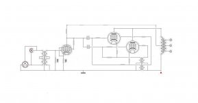
I dont know, but looks like I was focused on the pushpull CFB
but cross referenced feedback wouldn't be possible with SE design, would it ?
maybe I should have cross referenced grids to cathodes, Garter style
to balance the bias between the tubes
is there any kind of feedback from the added trafo ?
but cross referenced feedback wouldn't be possible with SE design, would it ?
maybe I should have cross referenced grids to cathodes, Garter style
to balance the bias between the tubes
is there any kind of feedback from the added trafo ?
Attachments

- Status
- This old topic is closed. If you want to reopen this topic, contact a moderator using the "Report Post" button.
- Home
- Amplifiers
- Tubes / Valves
- OPT with cathode feedback