I have an amplifier that has jumpers that are intended allow one to select between 6SN7 and 6SL7 for the first stage tube. Since I built a lightspeed clone I thought I'd give the 6SL7 a go for the extra gain. I first wanted to have a look at the loadline and I didn't like what I saw. I'm not really sure I drew them correctly, especially given how horrid the factory specs look.
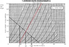
The first attachment is for the 6SL7 with a PV of 268, a 68K plate resistor and a 3 volt bias. I measured these values.
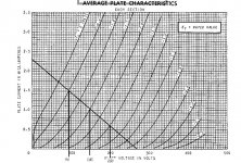
The second attachment is what I think might work better. It's still 268 PV but I changed the plate resistor to 200K and changed the bias to 1.5 volts.
Question is, did I do it correctly and is my version the best choice?
Thanks
The first attachment is for the 6SL7 with a PV of 268, a 68K plate resistor and a 3 volt bias. I measured these values.
The second attachment is what I think might work better. It's still 268 PV but I changed the plate resistor to 200K and changed the bias to 1.5 volts.
Question is, did I do it correctly and is my version the best choice?
Thanks
Attachments
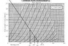
The 68k load line with bias at 3.5 V will result in quite a bit of distortion. Note how the load lines bunch up near the end of the load line.
It looks like the second load line (1.5 V) is actually 100 kOhm not 200 kOhm. But that looks like a reasonable operating point.
I've run 6SL7's at 1.7 V cathode bias (red LED) and a 2~3 mA CCS. Works like a charm.
~Tom
It looks like the second load line (1.5 V) is actually 100 kOhm not 200 kOhm. But that looks like a reasonable operating point.
I've run 6SL7's at 1.7 V cathode bias (red LED) and a 2~3 mA CCS. Works like a charm.
~Tom
It looks like the second load line (1.5 V) is actually 100 kOhm not 200 kOhm. But that looks like a reasonable operating point.
~Tom
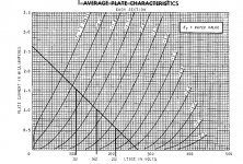
Yeah Tom, that's a typo but I had intended it to be 120K. 268/120=2.23ma
I used that resistance to get the load line more perpendicular to the lines of constant Ec.
I like your operating point better, see first attachment, as it is nearly equal each side of the bias voltage and with a higher bias value.
The second attachment is 2 volt bias which might work even better for me since I'm not using LEDs. Hummm...well maybe...
So, somewhere I got the idea that the load line should be perpendicular to the lines of constant Ec for lowest distortion, but I can't remember now where I got that idea. Is there any reason why that would be so?
Attachments
Last edited:
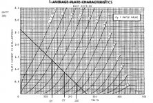
Do not forget to also consider your AC load-line.
The AC load will be the impedance of the load (next stage grid-leak) in parallel to the plate resistor.
Illustrated with the red line added to your chart.
If the load is 500K or higher, the effect will however be small.
--
SveinB.
The AC load will be the impedance of the load (next stage grid-leak) in parallel to the plate resistor.
Illustrated with the red line added to your chart.
If the load is 500K or higher, the effect will however be small.
--
SveinB.
Attachments
Last edited:
Do not forget to also consider your AC load-line.
The AC load will be the impedance of the load (next stage grid-leak) in parallel to the plate resistor.
Illustrated with the red line added to your chart.
If the load is 500K or higher, the effect will however be small.
--
SveinB.
Well, I had a different understanding of that. I was just reading in Morgan Jones that one uses anode resistance for the dynamic or AC loadline. That anode resistance was charted by drawing a line as shown in the attachment below. The anode resistance is the slope. I'm sure I'm confusing the two. Can you shed some more light on the subject?
It looks like you used about 350K for the grid-leak resistor for the red line - is that correct?
Attachments
So, somewhere I got the idea that the load line should be perpendicular to the lines of constant Ec for lowest distortion, but I can't remember now where I got that idea. Is there any reason why that would be so?
No reason. Generally, the lowest distortion will be with a horizontal load line (constant current plate load, infinite impedance into next stage). But, the question is: are you designing for lowest stage distortion, or lowest overall amplifier distortion? They are not necessarily the same things.
You can calculate the distortion from the plate curves and loadline. Look here in the section on loadlines, about halfway down the page: Steve's Tube Pages
Well, I had a different understanding of that. I was just reading in Morgan Jones that one uses anode resistance for the dynamic or AC loadline. That anode resistance was charted by drawing a line as shown in the attachment below. The anode resistance is the slope. I'm sure I'm confusing the two. Can you shed some more light on the subject?
If you have Jone's third edition, read page 118. It's in the section on the u-follower. He probably should have addressed it earlier in the discussion on loadlines.
Sheldon
There is also one very practical method to obtain best possible working condition.
Use potentiometers as a part of anode and cathode resistors. Then simply adjust both resistors to minimum distortion by using correct input voltage for the tube.
Then take the readings of pots and replace with fixed resistors.
Use potentiometers as a part of anode and cathode resistors. Then simply adjust both resistors to minimum distortion by using correct input voltage for the tube.
Then take the readings of pots and replace with fixed resistors.
There is also one very practical method to obtain best possible working condition.
Use potentiometers as a part of anode and cathode resistors. Then simply adjust both resistors to minimum distortion by using correct input voltage for the tube.
Then take the readings of pots and replace with fixed resistors.
I'll repeat the point I hinted at earlier, but a little more clear. We don't listen to stages - unless it's a single stage amp - we listen to the system. Sometimes distortion in one stage can cancel distortion in the following stage. This applies particularly for 2nd order distortion in a commonly used grounded cathode, driving a typical SET output. Checking distortion on the fly is a good idea, but you have to do the entire amp.
Interesting graphics on distortion: Harmonic Distortion Pictures
Sheldon
I find in general that 6SL7 sound much better and generate less distortion if the quiescent operating point is centered around 1.5 - 2mA - this is particularly the case where large voltage swings are required. (At 1mA you are not operating in the most linear region of the characteristic curves over significant voltage swings.)
Take heed of Sheldon's comments despite the above.
Take heed of Sheldon's comments despite the above.
Last edited:
Hello,
I agree with the thoughts of how the voltage amplifier stage integrates into the complete amplifier; more current and gm are better. The *SL7 is on the weak end of transductance scale. The Miller capacitance of the next stage needs careful consideration.
Load Lines are fine but incomplete theory. The next stage will be an active load. The load line is less a line than an ellipse.
DT
All just for fun!
Sometimes distortion in one stage can cancel distortion in the following stage.
Beautiful theory that works somehow with single sine signal.
With real signals (music) and real circuits every non-linear stage creates it's own IMD-spectrum that can not cancelled out in next stage. Contrary, the result after combining two non-linear stages in distortion cancelling purpose is worse than when simply using individually optimised, linear stages.
Theory or practice? I've done it and measured it. Not saying it's going to work every time, and it won't solve problems of gross distortion, so good design if each stage is important. But the amp's final output is what counts, and in fine tuning, it's the whole amp that has to be the subject.
Sheldon
Beautiful theory that works somehow with single sine signal.
With real signals (music) and real circuits every non-linear stage creates it's own IMD-spectrum that can not cancelled out in next stage. Contrary, the result after combining two non-linear stages in distortion cancelling purpose is worse than when simply using individually optimised, linear stages.
Hello,
Did I miss something? Did someone say to assemble the worst possible voltage gain stage and all the junk will cancel out in the power tube?
DT
All just for fun!
You can calculate the distortion from the plate curves and loadline. Look here in the section on loadlines, about halfway down the page: Steve's Tube Pages
If you have Jone's third edition, read page 118. It's in the section on the u-follower. He probably should have addressed it earlier in the discussion on loadlines.
Sheldon
Third edition, yes. Found it. Thanks. Steve's tube pages are some good reading too.
Last edited:
- Status
- This old topic is closed. If you want to reopen this topic, contact a moderator using the "Report Post" button.
- Home
- Amplifiers
- Tubes / Valves
- Did I do this loadline correctly